The best wire size formula for 60-degree threads is W = 0.57735 × P for metric threads (where P is the thread pitch in millimeters) and W = 0.57735 / n for Unified/imperial threads (where n is the number of threads per inch). Selecting this exact wire diameter ensures that the measuring wires contact the thread flanks precisely at the theoretical pitch line, minimizing measurement errors caused by flank angle deviations.
Accurate pitch diameter inspection requires matching the wire diameter to the thread pitch, measuring the dimension over wires (M) with a calibrated micrometer, and deciding whether quantitative three-wire pitch diameter verification or functional pass/fail gauging fits your production workflow. In this guide, you will learn the exact metric and imperial formulas, acceptable minimum and maximum wire size limits, step-by-step pitch diameter calculations, reference charts for common thread sizes, and how to decide between thread measuring wires and precision thread gauges on the shop floor.
The Best Wire Size Formula for 60-Degree Threads (Metric & Imperial)
For any symmetrical 60-degree screw thread—including the ISO Metric and Unified thread standards—the ideal measuring wire diameter is derived directly from the geometry of an equilateral triangle. Because the thread included angle is 60°, the half-angle (α) is 30°. In standard thread metrology, the constant 0.57735 equals 1 / (2 cos 30°), which positions the center of the wire so its contact points touch the thread flanks directly on the pitch diameter cylinder.
| Thread System | Best Wire Size Formula | Variable Definition | Unit of Output (W) |
|---|---|---|---|
| Metric Threads (ISO) | W = 0.57735 × P | P = Thread pitch (distance between adjacent crests) | Millimeters (mm) |
| Unified / Inch Threads (UN) | W = 0.57735 / n | n = Threads per inch (TPI) | Inches (in) |
For quick shop-floor estimates, machinists sometimes round the constant to 0.57735027 when working with high-precision calibration certificates, or 0.5774 for rough tooling checks. Always retain at least five decimal places (0.57735) when calculating measurement over wires (M) for tight-tolerance aerospace, automotive, or medical fasteners.
Why Pitch-Line Contact Matters (Plus Min/Max Wire Size Limits)
A measuring wire that contacts the thread flanks directly at the pitch line eliminates the influence of minor flank angle errors on the pitch diameter reading. When a wire is significantly larger or smaller than the calculated best wire size, two distinct measurement problems occur:
- Oversized wires: If the wire diameter is too large, the wire sits too high in the thread groove and may rest on the crest corner radius or burr rather than the straight flank, producing an artificially high micrometer reading.
- Undersized wires: If the wire diameter is too small, the wire drops deep into the thread root and can bottom out on the root fillet before touching both flanks, making the measurement invalid.
When an exact best-size wire is unavailable in your metrology kit, standard metrology practice allows alternative wire sizes within defined geometric boundaries:
- Minimum wire size (Wmin): Approximately 0.505 × P (or 0.505 / n). Below this limit, the wire risks contacting the root radius or failing to project above the major diameter crests for micrometer anvil clearance.
- Maximum wire size (Wmax): Approximately 0.90 × P (or 0.90 / n). Above this limit, the wire contacts the thread flanks too close to the crest truncation.
How to Calculate Pitch Diameter Using the Three-Wire Method
Calculating the best wire size is the setup step; the actual inspection goal is verifying whether the workpiece pitch diameter (E) falls within specification. Once you place two wires in adjacent grooves on one side of the external thread and one wire in the opposing groove on the other side, follow these four steps:
- Select and verify wire diameter (W): Choose a calibrated three-wire set matching the calculated best wire size (or within the Wmin to Wmax range) and record the actual calibrated mean wire diameter printed on the certificate.
- Measure dimension over wires (M): Position the three wires cleanly in the thread grooves and measure across the outside of the wires using a flat-anvil outside micrometer with consistent measuring force.
- Apply the 60-degree measurement over wires formula: Use the standard 60-degree equation relating measurement over wires (M), pitch diameter (E), actual wire diameter (W), and pitch (P):
- Solve for actual pitch diameter (E): Rearrange the formula to isolate the workpiece pitch diameter.
M = E + 3W − 0.866025P
E = M − 3W + 0.866025P
(For Unified inch threads, substitute P = 1 / n, giving E = M − 3W + 0.866025 / n.)
Worked Calculation Example: M10 × 1.5 Metric External Thread
Suppose you are inspecting an M10 × 1.5 external thread with a target pitch diameter (E) specification of 8.862 mm to 8.994 mm (standard 6g tolerance class):
- Calculate best wire size: W = 0.57735 × 1.5 mm = 0.8660 mm.
- Measure over wires (M): using calibrated 0.8660 mm wires, your micrometer reads M = 10.225 mm.
- Calculate actual pitch diameter (E):
E = 10.225 − (3 × 0.8660) + (0.866025 × 1.5)
E = 10.225 − 2.5980 + 1.2990 = 8.926 mm
Since 8.926 mm sits squarely between 8.862 mm and 8.994 mm, the pitch diameter is within tolerance.
(Note: for threads with large lead angles—such as multi-start threads or coarse pitches on small diameters—a rake correction factor should be applied according to ASME B1.2 or ISO 1502 guidelines.)
Best Wire Size Chart for Common Metric and Unified (UN) Threads
The reference tables below provide pre-calculated best wire diameters (W) and the pitch constant (0.866025P) for standard 60-degree metric pitches and Unified threads per inch (TPI).
Table A: Common Metric Thread Pitches (ISO 60°)
| Metric Pitch (P) | Common Thread Sizes (Coarse / Fine) | Best Wire Size (W = 0.57735P) | Pitch Constant (0.866025P) |
|---|---|---|---|
| 0.50 mm | M3 × 0.5 | 0.2887 mm | 0.4330 mm |
| 0.70 mm | M4 × 0.7 | 0.4041 mm | 0.6062 mm |
| 0.80 mm | M5 × 0.8 | 0.4619 mm | 0.6928 mm |
| 1.00 mm | M6 × 1.0, M8 × 1.0 | 0.5774 mm | 0.8660 mm |
| 1.25 mm | M8 × 1.25, M10 × 1.25 | 0.7217 mm | 1.0825 mm |
| 1.50 mm | M10 × 1.5, M12 × 1.5, M14 × 1.5 | 0.8660 mm | 1.2990 mm |
| 1.75 mm | M12 × 1.75 | 1.0104 mm | 1.5155 mm |
| 2.00 mm | M14 × 2.0, M16 × 2.0 | 1.1547 mm | 1.7321 mm |
| 2.50 mm | M18 × 2.5, M20 × 2.5 | 1.4434 mm | 2.1651 mm |
| 3.00 mm | M24 × 3.0, M27 × 3.0 | 1.7321 mm | 2.5981 mm |
Table B: Common Unified Thread Pitches (UN / UNC / UNF 60°)
| Threads Per Inch (n) | Common Thread Sizes | Best Wire Size (W = 0.57735/n) | Pitch Constant (0.866025/n) |
|---|---|---|---|
| 32 TPI | #6-32 UNC, #8-32 UNC, #10-32 UNF | 0.01804 in | 0.02706 in |
| 28 TPI | 1/4″-28 UNF | 0.02062 in | 0.03093 in |
| 24 TPI | #10-24 UNC, 5/16″-24 UNF, 3/8″-24 UNF | 0.02406 in | 0.03608 in |
| 20 TPI | 1/4″-20 UNC, 7/16″-20 UNF, 1/2″-20 UNF | 0.02887 in | 0.04330 in |
| 18 TPI | 5/16″-18 UNC, 9/16″-18 UNF, 5/8″-18 UNF | 0.03208 in | 0.04811 in |
| 16 TPI | 3/8″-16 UNC, 3/4″-16 UNF | 0.03608 in | 0.05413 in |
| 14 TPI | 7/16″-14 UNC, 7/8″-14 UNF | 0.04124 in | 0.06186 in |
| 13 TPI | 1/2″-13 UNC | 0.04441 in | 0.06662 in |
| 11 TPI | 5/8″-11 UNC | 0.05249 in | 0.07873 in |
| 10 TPI | 3/4″-10 UNC | 0.05774 in | 0.08660 in |
Three-Wire Method vs. Thread Gauges: Which Should Your Shop Use?
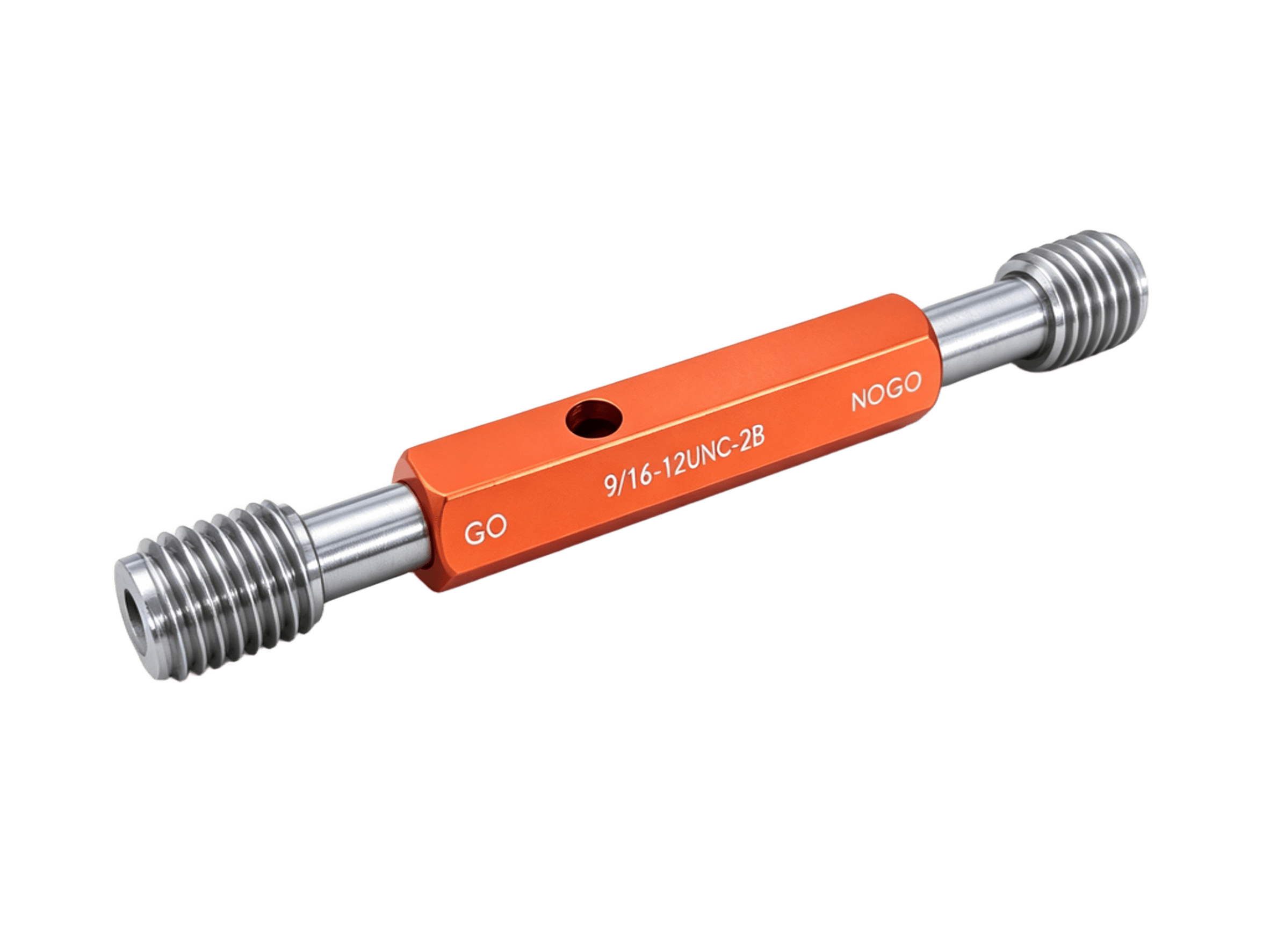
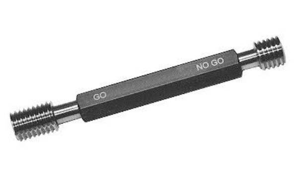
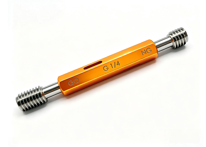
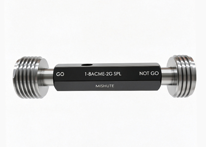
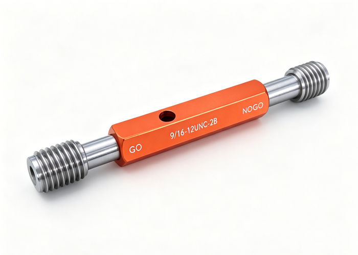
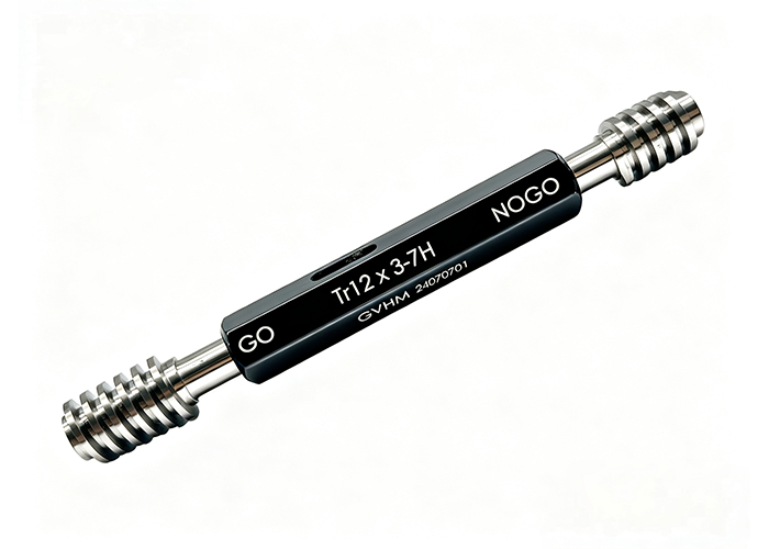
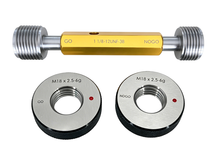
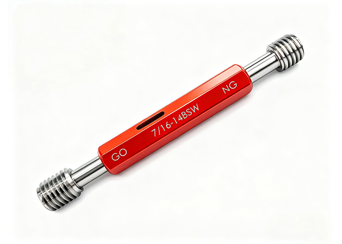
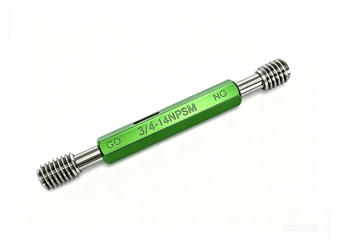
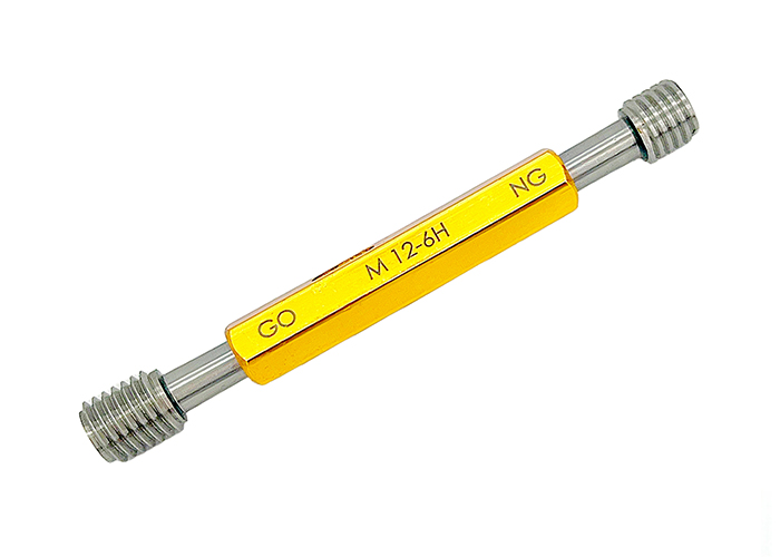
While the three-wire method delivers exact numerical pitch diameter values for external threads, holding three loose wires and a micrometer against every part is too slow for serial production and impossible for internal tapped holes. In commercial manufacturing environments, quality teams balance three-wire measurement with fixed-limit Go/No-Go thread gauges (thread plug gauges and thread ring gauges) based on inspection speed, feature geometry, and compliance requirements.
| Evaluation Criteria | Three-Wire Thread Measurement | Fixed-Limit Thread Gauges (Plug & Ring) |
|---|---|---|
| Measurement Output | Quantitative (exact numerical pitch diameter value) | Qualitative (functional Go/No-Go pass/fail verdict) |
| Thread Applicability | External threads only | Both internal threads (plug gauges) and external threads (ring gauges) |
| Inspection Speed | Slow (requires wire placement, micrometer reading, and math) | Fast (seconds per part on the CNC machine or inspection bench) |
| Error Detection Scope | Measures local pitch diameter only; does not catch cumulative pitch error over engagement length | Go gauge checks maximum material limit (functional size including pitch and flank angle errors); No-Go checks minimum material pitch diameter |
| Operator Skill Requirement | High (sensitive to anvil alignment, measuring force, and cleanliness) | Moderate (standardized feel and turn-count rules) |
| Best Production Fit | First-article inspection (FAI), tool offset adjustments, custom/one-off pitches, and gauge calibration | High-volume production runs, internal threads, and final outgoing quality control (OQC) |
Decision Framework for Machine Shops and QC Teams
- Use the three-wire method for setup and variable data: When dialing in CNC lathe thread-turning offsets, validating a custom non-standard external thread pitch, or recording variable Statistical Process Control (SPC) data, use calibrated measuring wires with the best wire size formula.
- Use thread ring and plug gauges for serial production: Once the CNC process is stable, switch to fixed-limit thread ring gauges (for external threads) and thread plug gauges (for internal threads) so operators can verify functional assembly compatibility in seconds without stopping spindle output. The choice between the two gauge families is covered in detail by our thread plug gauge vs. thread ring gauge selection guide, and operators should follow a documented Go/No-Go gauging operating procedure to keep pass/fail judgments consistent across shifts.
- Combine both methods for tight-tolerance parts: For critical aerospace, hydraulic, or safety-joint components, use three-wire measurement during first-article sign-off to verify true pitch diameter, and deploy calibrated Go/No-Go gauges for 100% or sampling-based batch verification. Correct handling matters on the shop floor—master the proper thread ring gauge technique before rolling fixed-limit gauges out to production.
Frequently Asked Questions About 60-Degree Thread Wire Formulas
Can the 0.57735 best wire size formula be used for internal threads?
No. The three-wire method physically requires placing wires into external thread grooves and measuring across the outside diameter with a micrometer, so it cannot be applied to internal nuts or tapped holes. Internal threads are inspected using standard and custom thread plug gauges, thread micrometers with internal ball tips, or optical/CMM scanning systems depending on bore size and tolerance requirements. For a structured overview, see our guide to internal vs. external thread inspection.
Does the best wire size formula change for Acme (29°) or Whitworth (55°) threads?
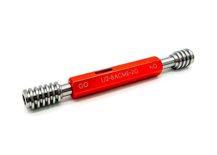
Yes. The constant 0.57735 applies strictly to symmetrical threads with a 60° included angle (1 / 2 cos 30°). For 55° Whitworth/BSP threads, the best wire size constant changes to 0.56369 × P (1 / 2 cos 27.5°). For 29° Acme trapezoidal threads, the constant becomes 0.51645 × P (1 / 2 cos 14.5°).
What if my thread measuring wires are slightly worn or differ from the theoretical best size?
Always use the actual calibrated wire diameter certified on your wire set’s inspection report rather than the nominal calculated value when computing E = M − 3W + 0.866025P. Because the wire diameter (W) is multiplied by 3 in the measurement-over-wires equation, even a 0.002 mm error in wire diameter creates a 0.006 mm error in your calculated pitch diameter. Learn how to audit your measuring tools by reading calibration certificates, and set an appropriate recalibration frequency so worn wires never silently distort your results.
Key Takeaways
- Core best wire size formula: For all 60-degree threads, calculate the ideal wire diameter using W = 0.57735 × P (Metric) or W = 0.57735 / n (Unified/Inch) so the wires touch the thread flanks directly on the pitch line.
- Acceptable wire size boundaries: If exact best-size wires are unavailable, alternative wires must stay between Wmin ≈ 0.505P and Wmax ≈ 0.90P to prevent bottoming out in the thread root or riding on the crest corners.
- Pitch diameter formula: Calculate true external pitch diameter from your micrometer measurement over wires (M) using E = M − 3W + 0.866025P, always substituting the actual calibrated wire diameter for W.
- Shop-floor workflow selection: Use three-wire measurement for first-article verification, CNC lathe offset tuning, and custom external pitches; use Go/No-Go thread gauges for rapid batch inspection and all internal threads.
Streamline Your Thread Inspection Workflow with MIHE
Calculating the right wire diameter keeps your external thread setup accurate, while pairing variable metrology with reliable fixed-limit gauging keeps your production line moving without bottlenecks. Whether your facility inspects standard ISO Metric and Unified threads or custom-engineered profiles, confirming the exact thread standard, pitch, tolerance class (such as 6g/6H or 2A/2B), and required calibration documentation before ordering prevents inspection delays on the shop floor. For made-to-print requirements, review our custom thread gauge specifications for OEM orders.
Explore precision thread gauges or share your thread drawings and tolerance specifications with the MIHE engineering team to confirm the right gauging configuration for your inspection workflow.