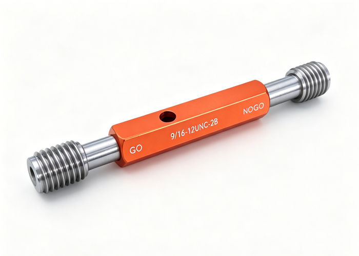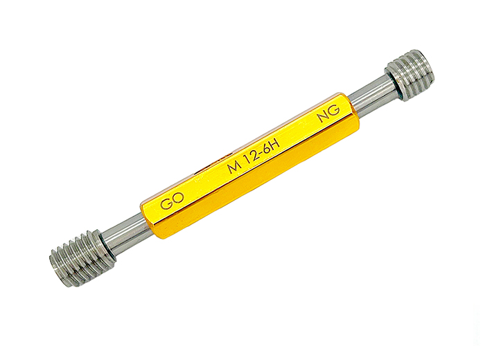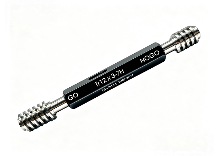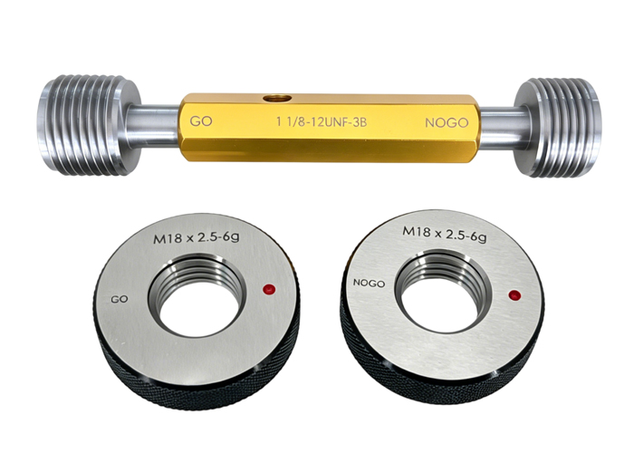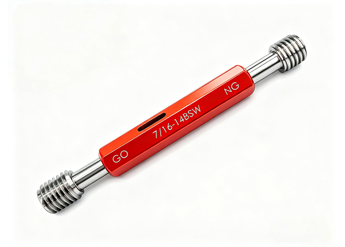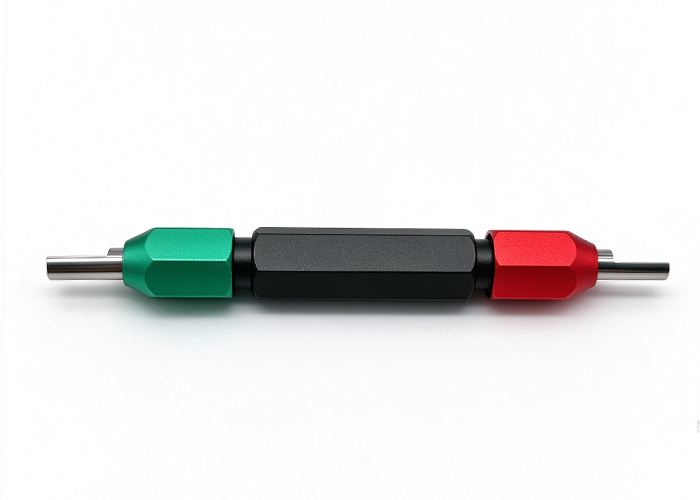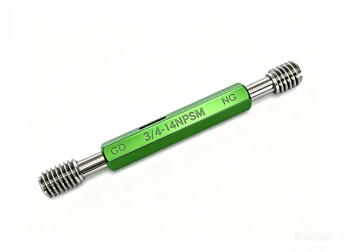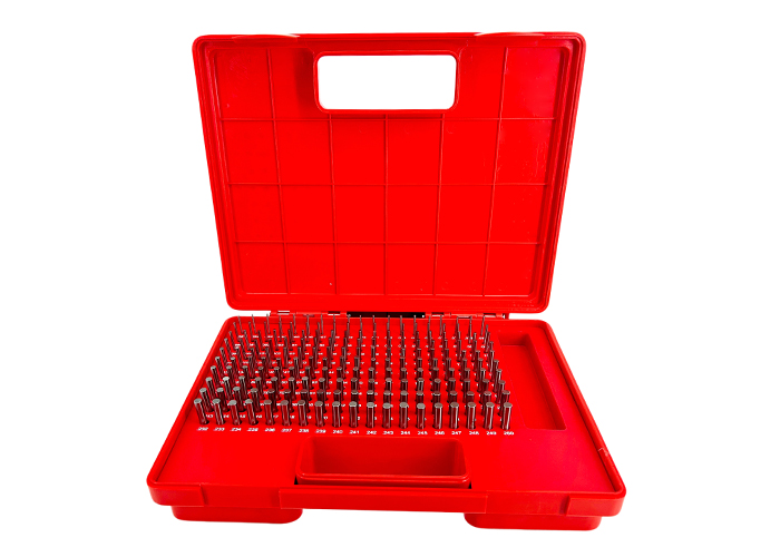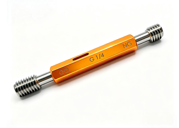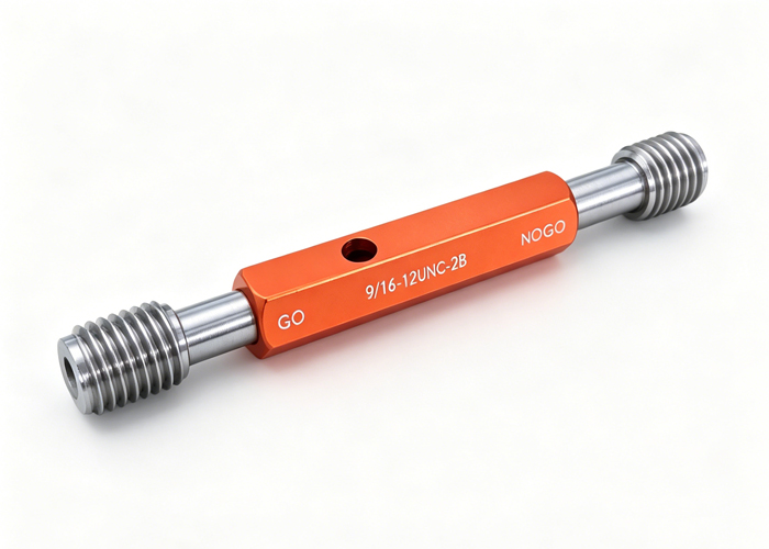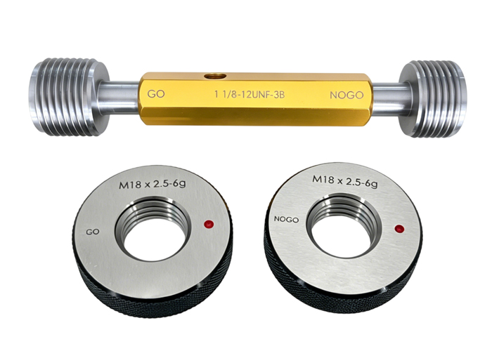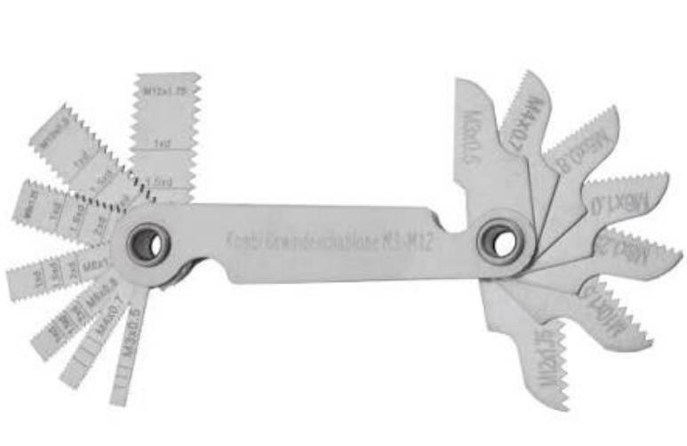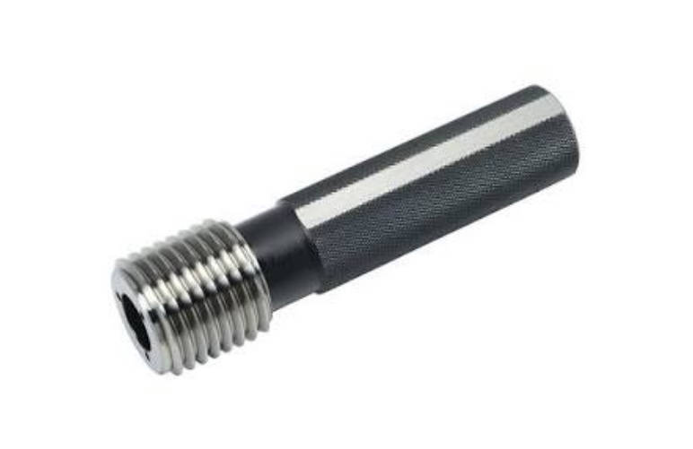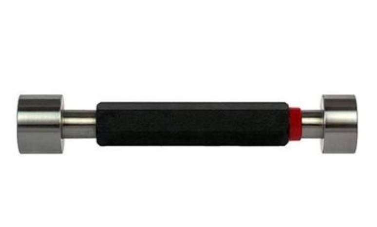
Using a go/no-go fixed-limit gauge requires precise manual control rather than mechanical force. To use thread gauges correctly, an inspector must clean the mating threads, align the gauge coaxially with the part, and turn the member using light, two-finger torque. The Go gauge must enter and pass smoothly through the full length of engagement without binding, while the No-Go gauge must not engage past the maximum turn limit specified by the governing standard (typically two to three complete turns).
Applying excessive torque, inspecting parts with burrs, or forcing a misaligned gauge distorts inspection results, leads to the false acceptance or rejection of parts, and causes permanent tool wear. This technical guide outlines the standard operating procedures (SOP) for thread plug and ring gauges, clarifies international acceptance limits, and highlights practical maintenance rules for shop-floor quality control.
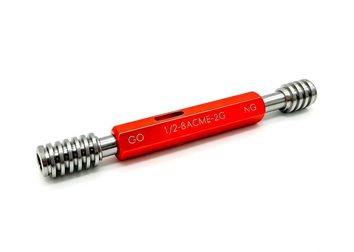
The Fundamentals of Go/No-Go Thread Inspection: Why Proper Technique Matters
Thread gauging relies on a functional limit system designed to confirm whether internal and external threads fall within their specified dimensional tolerances. A standard gauge set consists of two distinct members:
The Go Member: Verifies the maximum material condition (MMC). For an internal thread, this evaluates the minimum pitch diameter and minimum major diameter; for an external thread, it evaluates the maximum pitch diameter and maximum minor diameter. It also confirms lead, flank angle, and taper compliance across the full design length of engagement.
The No-Go (or HI / NOT GO) Member: Verifies the minimum material condition (LMC). It inspects whether the thread’s functional pitch diameter has exceeded the allowable upper limit on internal threads or the lower limit on external threads.
| Gauge Member | Material Condition Verified | Pass Condition |
| Go Gauge | Maximum Material Condition (MMC) | Must assemble freely through the entire thread engagement. |
| No-Go Gauge | Least Material Condition (LMC) | Must not seat; entry restricted to standard turn limits (≤ 2–3 turns). |
Improper operator technique directly skews these functional boundaries. Forcing a No-Go gauge through an undersized hole can shave metal away, causing false passes. Conversely, presenting a gauge at an angle can jam against the initial thread crest, falsely rejecting parts that sit within specification. Deploying certified, durable and certified thread gauges preserves product integrity only when operators follow standard testing motions.
Standard Operating Procedure: How to Inspect Internal Threads with Plug Gauges
Internal threads (tapped holes, threaded bosses, internal connectors) require cylindrical thread plug gauges. Follow this sequence for consistent quality verification.
Step 1: Pre-Inspection Cleaning and Visual Deburring
Residual metal shavings, chips, and abrasive cutting fluids trapped in tapped blind holes invalidate gauge readings.
Clear the hole using filtered compressed air or a soft-bristle nylon brush.
Inspect the hole mouth visually or under magnification. Ensure that chamfers are uniform and free of rolled-over burrs caused by dull taps.
Apply a light film of clean, low-viscosity spindle oil or calibration fluid to the gauge member to prevent friction galling, particularly when gauging stainless steel, aluminum, or titanium alloys.
Step 2: Engaging the Go Plug Gauge (Full Engagement Rule)
Align the axis of the Go plug gauge parallel to the axis of the tapped hole.
Rotate the gauge backwards (counter-clockwise) gently until you feel the starting thread drop into alignment.
Turn the gauge clockwise using only light finger pressure (the index finger and thumb).
Pass Criteria: The Go member must rotate freely through the full specified depth of the internal thread without the application of wrist leverage, wrenches, or impact. If the gauge seizes before reaching the target depth, the thread is undersized, tapered, or obstructed by root packing.
Step 3: Applying the No-Go Plug Gauge (The Turn-Limit Rule)
Present the No-Go plug gauge (identified by a red marking ring or a distinct notch on the handle) to the clean part opening.
Rotate the gauge gently using the same two-finger grip.
Pass Criteria: The No-Go gauge must meet positive resistance at the entry. It should not turn into the hole beyond the specific thread-turn threshold set by the drawing standard (detailed below). If it threads fully into the part, the internal pitch diameter is oversized, and the component must be flagged as non-conforming.
For specialized threading profiles or high-volume machining setups, operations should specify standard and custom thread plug gauges that match the exact class of fit (such as 6H for metric or 2B/3B for unified threads).
Standard Operating Procedure: How to Inspect External Threads with Ring Gauges
External threads on bolts, studs, shafts, and turned parts require adjustable or solid thread ring gauges. Ring gauges are sensitive to axial alignment errors and drop damage.
| Inspection Stage | Action & Observation | Result & Decision |
| Preparation | Deburr and degrease workpiece thoroughly | Ensures true flank contact without chip interference |
| Go Ring Gauge Test | Thread gauge onto part with light finger torque across full length | Pass: Spins smoothly across full engagement Fail: Binds or seizes (Thread oversized, lead error, or tapered) |
| No-Go Ring Gauge Test | Attempt to thread gauge onto the leading threads | Pass: Stops immediately or within standard turn limit Fail: Spins past allowable turns (Thread undersized or worn pitch) |
Verifying External Threads with the Go Ring Gauge
Clean the external thread thoroughly to remove swarf, grinding dust, or heavy particulate coatings.
Hold the external thread perpendicular to the face of the Go ring gauge.
Thread the ring gauge onto the workpiece manually. The gauge must pass smoothly across the complete threaded length without binding.
If excessive resistance occurs at a specific point, inspect the component for lead error, damaged thread flanks, out-of-roundness, or taper from tool deflection during turning.
Testing Minimum Material Condition with the No-Go Ring Gauge
Present the No-Go ring gauge to the component.
Attempt to thread the ring onto the part using gentle finger rotation.
The No-Go gauge should stop immediately upon contact or within the permissible partial turn allowance. If the gauge spins easily onto the body of the fastener, the pitch diameter has been cut below the minimum tolerance limit, reducing shear strength.
In high-throughput environments, utilizing precision-ground precision thread ring gauges maintains dimensional repeatability over extended production runs.
Acceptance Criteria: Exactly How Many Turns Can a No-Go Gauge Enter?
A frequent debate on the shop floor concerns whether a No-Go gauge is permitted to enter a part at all. Because lead chamfers on both the gauge and the workpiece create an entry transition zone where full thread profiles have not yet formed, major manufacturing standards define distinct engagement tolerances.
| Standard Specification | Applicable Thread System | Permissible No-Go Engagement Criteria |
| ASME / ANSI B1.2 | Unified National (UN / UNC / UNF) | The No-Go gauge may enter, but must not exceed three (3) complete turns before encountering definite drag or stopping. |
| ISO 1502 | Metric (M Profile) | The gauge must not enter by more than two (2) complete turns. If the workpiece has fewer than three threads total, entry must not exceed one full turn. |
| BS 919 | British Standard (BSW / BSF) | Engagement should not exceed two (2) turns, subject to specific contractual drawing annotations. |
Practical Considerations for the Turn Limit Rule
Counting Turns: The count begins from the position where the thread first catches, not from initial physical contact against the chamfer face. When withdrawing the gauge, count the rotations back to the point of disengagement to verify compliance.
Thin-Walled Components: In sheet metal stampings, thin tubes, or soft ductile materials (such as copper or unreinforced polymers), clamping deformation can turn round holes oval. In these cases, even a single-turn engagement must be evaluated alongside roundness checks to prevent false passes.
Incomplete Starting Threads: If a tapped hole features a deep 45-degree countersink or a ragged runout thread, the No-Go gauge may seat deeper than expected without the pitch diameter actually being out of specification. In critical cases, evaluate parts using optical comparators or coordinate measuring machines (CMM) alongside custom thread inspection gauges.
5 Common Mistakes That Damage Thread Gauges and Skew Inspection Results
Tool longevity and inspection reliability depend on avoiding several common operator errors.
| Operator Mistake | Physical Consequence | Corrective SOP Practice |
| 1. Applying High Insertion Torque | Causes flank galling, micro-welding, and false passes | Apply light two-finger torque only; never use wrenches or wrist force |
| 2. Inspecting Dirty Parts with Burrs | Embedded metal chips abrade gauge teeth and ruin calibration | Solvent clean, deburr, and blow dry before inspection |
| 3. Neglecting Thermal Expansion | Hot workpieces contract after cooling, skewing critical microns | Allow parts and gauges to equalize to 20°C (68°F) before testing |
| 4. Off-Axis Alignment | Cross-threading and chipped leading threads | Align gauge and part axes strictly parallel before turning |
| 5. Unchecked Tool Wear | Out-of-spec components pass undetected into assembly lines | Maintain scheduled calibration tracking and wear allowance checks |
Mistake 1: Forcing the Gauge Beyond Light Finger Pressure
Applying excessive wrist force, hand palms, or leverage tools drives the hardened steel gauge into interference fits. This practice causes micro-welding and thread galling, particularly on stainless steels. A gauge should never be forced; if it does not turn smoothly under light finger pressure, the part has failed the test.
Mistake 2: Inspecting Dirty or Unfinished Parts with Burrs
Using a thread plug or ring gauge as a deburring tool rapidly abrades the gauge teeth. Microscopic chips wedged between the gauge and part flanks act as cutting agents, stripping away the calibrated wear allowance on the gauge. Always deburr and clean components prior to inspection.
Mistake 3: Neglecting Thermal Expansion (Measuring Hot Workpieces)
Parts taken directly from a CNC machining center, grinding line, or wash station retain thermal energy. A hot aluminum part will expand significantly relative to a steel gauge held at room temperature. An internal thread measured hot may accept a Go gauge, but will shrink below tolerance once cooled to the international reference temperature of 20°C (68°F), causing unexpected assembly failures downstream.
Mistake 4: Dropping or Side-Loading the Gauge Axis
Thread ring and plug gauges are made from GCR15. While extremely wear-resistant, they are brittle. Dropping a gauge onto a concrete floor or steel table can micro-fracture the leading threads or knock adjustable ring gauges out of round. Similarly, starting a gauge at an angle cross-threads the part and damages the lead crests of the tool.
Mistake 5: Failing to Track Gauge Wear and Calibration Cycles
Because Go gauges experience contact friction across every inspected part, they wear down continuously. Over time, an internal Go plug gauge becomes smaller, eventually rejecting parts that sit within legitimate design tolerances. Conversely, a No-Go gauge wears larger, eventually accepting out-of-spec parts. Facilities must log cycle counts and deploy wear-resistant thread gauges with defined wear allowances.
Preserving Accuracy: Storage, Cleaning, and Calibration Frequency
Maintaining dimensional stability requires an organized tool maintenance and calibration program.
Cleaning and Storage Protocols
Post-Shift Cleaning: Wipe all gauges clean using lint-free cloths soaked in mineral spirits or fast-evaporating solvent degreasers to remove swarf, fingerprints, and coolant residue.
Corrosion Inhibition: Finger acid accelerates steel oxidation. Before returning tools to storage, coat surfaces with a clean rust preventative oil or microcrystalline wax.
Segregated Storage: Store gauges in individual fitted wooden boxes, molded silicone sleeves, or dedicated tool drawers with dividers. Never stack bare thread gauges loosely in bins where their threads can strike one another.
Establishing Calibration Intervals
Calibration frequency must balance regulatory compliance (ISO 9001, IATF 16949) with actual shop-floor wear cycles:
| Operating Environment | Usage Frequency | Recommended Calibration Interval |
| High-Volume Production | > 500 inspections per day | Monthly to Quarterly |
| Medium Production / CNC Cells | 50 – 200 inspections per day | Semi-Annually |
| Toolroom / Low-Volume Quality Lab | Intermittent or batch verification | Annually |
| Master Reference Gauges | Calibration laboratory use only | Every 2 to 3 Years |
When an active tool shows visual scratches, burrs, or fails periodic pitch diameter measurement via the three-wire method, retire the gauge immediately. Contacting an established industrial thread gauge manufacturer MIHE ensures replacement units meet certified class tolerances with traceable documentation.
Frequently Asked Questions About Thread Gauge Operations
Can thread gauges be used without lubrication?
Yes, dry inspection is acceptable if the parts are thoroughly cleaned and the alloy does not tend to gall. However, applying a drop of light, residue-free mineral oil or non-gumming inspection fluid reduces friction, protects precision-ground flank surfaces, and extends gauge service life—especially when checking soft aluminum, titanium, or austenitic stainless steel threads.
What is the functional difference between a thread plug gauge and a thread ring gauge?
A thread plug gauge inspects female (internal) threads, such as tapped holes and threaded sleeves, using external helical ground teeth. A thread ring gauge inspects male (external) threads, such as bolts, cap screws, and turned shafts, using internal precision threads. Both rely on complementary Go and No-Go members to verify pitch diameter and material limits.
What should an operator do if a thread gauge gets jammed in a part?
Never use a hammer, vise grip, or pipe wrench to break a stuck gauge free. Mechanical force will deform the workpiece and permanently damage the gauge flanks. Instead, apply a penetrating lubricant directly to the interface, allow it to settle for several minutes, apply mild localized cooling to the plug gauge or gentle warming to the housing, and back the tool out smoothly by hand using an axial twisting motion.
How can a shop determine if a thread gauge is worn beyond acceptable limits?
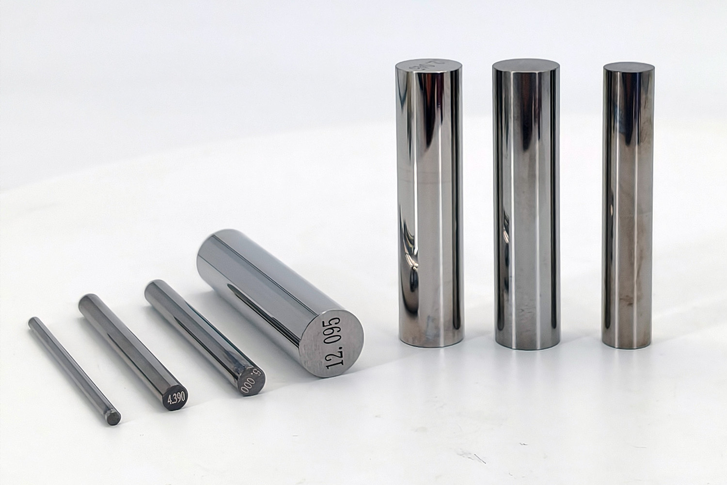
A visual check cannot verify dimensional drift. Go and No-Go plug gauges must be evaluated using the three-wire method on a calibrated micrometer or supermicrometer to measure the single pitch diameter. Ring gauges are evaluated using calibrated master setting plug gauges (truncated and full-form setting plugs). If the master plug passes through a locked ring gauge beyond the allowable tension, the ring gauge must be adjusted or retired.
Upgrade Your Shop-Floor Inspection with High-Precision Tooling
Adhering to standard operating procedures protects manufacturers from costly assembly failures, reduces part scrap rates, and extends the operational life of gauging tools. Consistent inspection relies on disciplined operator habits: thorough part cleaning, delicate finger-feel rotation, strict adherence to international turn limits, and structured calibration schedules.
When project drawings specify tight tolerance classifications, specialized thread forms, or demanding wear conditions, partnering with an experienced gauge manufacturer ensures inspection reliability. Explore MIHE’s comprehensive catalog of certified thread gauges to review technical specifications, select standard plug and ring configurations, or request custom tooling solutions designed for your production requirements.
Key Takeaways
Dual-Function Verification: Go gauges verify Maximum Material Condition (MMC) across the full length of engagement; No-Go gauges verify Minimum Material Condition (LMC) at the pitch diameter.
Two-Finger Operation: Never force a thread gauge with mechanical tools or heavy wrist torque; use light finger pressure to prevent galling and false dimensional passes.
Permissible Turn Limits: Under ISO 1502, a No-Go gauge must not engage past 2 complete turns; under ASME B1.2, engagement must not exceed 3 complete turns.
Pre-Inspection Cleaning: Chips, swarf, and burrs abrade precision-ground gauge flanks, causing false rejections and premature tool wear.
Scheduled Calibration: Track inspection cycles to recalibrate or replace worn gauges before out-of-spec components reach assembly lines or customers.
FAQ
Q: Can thread gauges be used without lubrication?
A: While dry inspection is possible on clean components, applying a light film of low-viscosity spindle oil prevents friction galling and extends the working life of the gauge flanks.
Q: What is the main difference between thread plug and ring gauges?
A: Thread plug gauges inspect internal (female) tapped threads, whereas thread ring gauges verify external (male) threaded fasteners and shafts.
Q: What is the proper procedure for a jammed thread gauge?
A: Apply penetrating fluid, allow temperature equalization, and extract the gauge manually without applying impact tools or mechanical wrenches.
Q: When should a thread gauge be removed from service?
A: Remove gauges from service when calibration measurements (via the three-wire method or setting master plugs) indicate that pitch diameter wear has exceeded drawing tolerances.