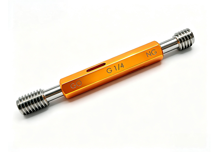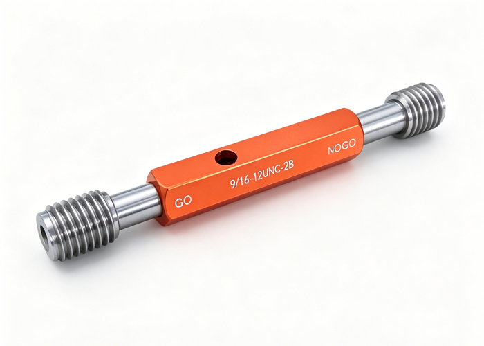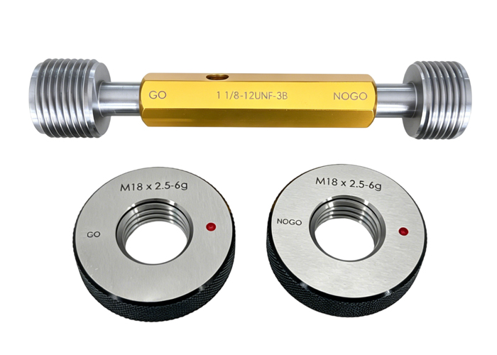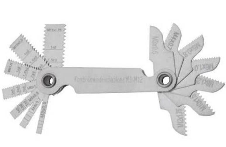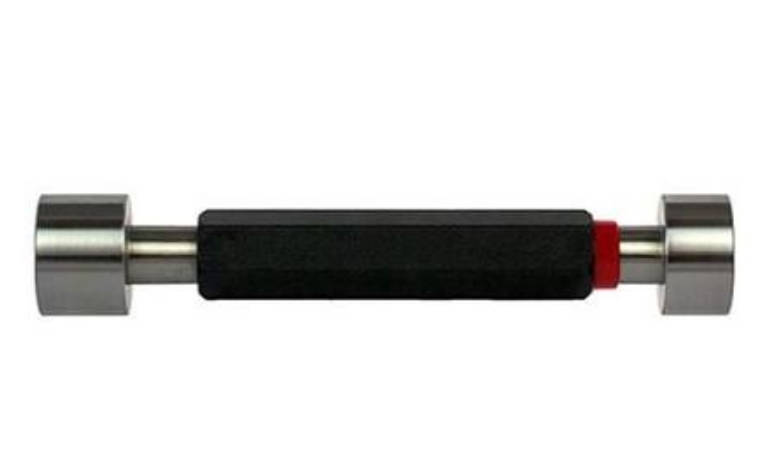
Go/No-Go thread gauges are fixed-limit inspection tools used to determine whether a manufactured thread remains within its permitted acceptance limits.
The GO gauge should engage the product thread as required by the applicable standard. The NO-GO gauge should not engage beyond the permitted limit.
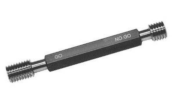
A threaded part is normally accepted only when the GO gauge passes and the NO-GO gauge does not pass beyond the allowed engagement.
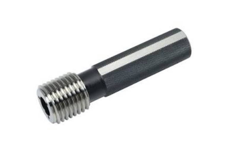
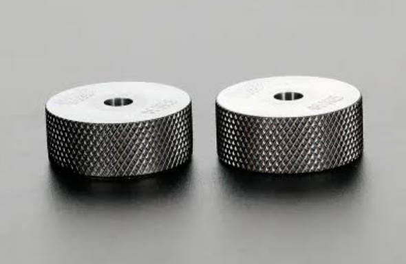
For internal threads, the inspection tool is usually a thread plug gauge. For external threads, it is usually a thread ring gauge.
| Workpiece Thread | GO/NO-GO Gauge Type | Typical Parts |
| Internal thread | Thread plug gauge | Tapped holes, nuts, threaded inserts |
| External thread | Thread ring gauge | Bolts, studs, shafts, male fittings |
International gauging standards define gauges for distinguishing compliant and noncompliant internal and external threads. ISO 1502 covers ISO general-purpose metric threads, while ASME B1.2 addresses gauging for Unified inch screw threads.
The Two-Decision Inspection System
A Go/No-Go inspection does not produce a numerical measurement such as 10.012 mm or 0.3942 inch. It produces two separate decisions:
- Does the GO gauge engage correctly?
- Does the NO-GO gauge remain outside the prohibited engagement zone?
Both decisions are necessary.
A part that passes only one side of the inspection has not completed the full acceptance check.
Decision 1: The GO Gauge
The GO gauge checks the functional maximum-material condition of the thread.
In practical terms, it helps determine whether excessive material, an incorrect thread form or another cumulative error prevents assembly with a conforming mating thread.
For an internal thread, excessive material may make the threaded opening functionally too small. For an external thread, excessive material may make the threaded shaft functionally too large.
The GO gauge should generally engage across the required functional thread length using controlled manual pressure.
Decision 2: The NO-GO Gauge
The NO-GO gauge checks the opposing thread limit.
It helps detect a thread that has become too loose because insufficient material remains at the relevant functional diameter.
For an internal thread, this may mean the thread is functionally too large. For an external thread, it may mean the thread is functionally too small.
The NO-GO gauge may be allowed limited initial engagement, depending on the thread system, gauge type and governing standard. It should not pass through the complete functional thread length.
“NO-GO” does not always mean that the gauge must make zero contact; it means that engagement must not exceed the limit specified by the applicable standard.
Internal Thread Inspection: Using a GO Thread Plug Gauge
Internal threads are found in components such as:
- Tapped holes
- Nuts
- Threaded inserts
- Hydraulic manifolds
- Engine housings
- Medical components
- Internally threaded fittings
A thread plug gauge has an external gauging thread that screws into the internal product thread.
Step 1: Confirm the Gauge Marking
Before inserting the gauge, compare its marking with the engineering drawing.
Check the complete designation, including:
- Nominal thread size
- Pitch or threads per inch
- Thread system
- Internal tolerance class
- Right-hand or left-hand direction
- GO or NO-GO identification
For example, an M10 × 1.5-6H gauge cannot be substituted with an M10 × 1.25-6H gauge. The nominal diameter is the same, but the pitch is different.
Step 2: Apply the GO Plug
Align the GO plug with the internal thread and turn it using normal finger pressure.
For a conforming thread, the GO member should engage through the required threaded length according to the relevant inspection procedure.
Do not use:
- Pliers
- A wrench
- Impact force
- Excessive hand torque
- The gauge as a thread-cleaning tool
A GO thread plug gauge that cannot engage correctly indicates that the internal thread may be functionally undersized, damaged, contaminated or incorrectly manufactured.
Step 3: Investigate Resistance
When a GO plug does not enter, do not immediately adjust the machining process.
First check for:
- Chips inside the hole
- Burrs at the thread entrance
- Damaged first threads
- Coating accumulation
- Incorrect gauge identification
- Misalignment between the gauge and hole
- Temperature differences
- A worn or damaged gauge
If these causes are excluded, the manufacturing process may have produced an unacceptable thread.
Step 4: Apply the NO-GO Plug
After the GO result is confirmed, apply the NO-GO member with the same controlled technique.
The NO-GO member should not engage beyond the limit defined by the governing thread standard and work instruction.
MISHUTE describes its Unified thread gauge markings with a GO member intended for full engagement and a NO-GO member restricted to limited engagement. The exact acceptance rule should still be matched to the specified thread system rather than applied universally. (mishute.com)
External Thread Inspection: Using a GO Thread Ring Gauge
External threads appear on:
- Bolts
- Screws
- Studs
- Threaded shafts
- Male connectors
- Pipe fittings
- Precision fasteners
A thread ring gauge has an internal gauging thread that screws over the external workpiece thread.
Step 1: Match the External Thread Class
The ring gauge must match an external thread designation.
For example:
- M12 × 1.75-6g: external metric thread
- 1/2-13 UNC-2A: external Unified thread
An internal tolerance class such as 6H or 2B should not be used to order a working ring gauge for an external product thread.
Step 2: Apply the GO Ring
Place the GO ring squarely over the external thread and rotate it using controlled manual force.
The GO ring should pass across the required threaded length without binding.
Failure may result from:
- An oversized functional thread
- Incorrect pitch
- Excessive plating
- Burrs on the thread crest
- Damaged flanks
- Lead error
- Incorrect thread rolling or cutting
- Ring gauge wear or incorrect setting
Step 3: Apply the NO-GO Ring
The NO-GO ring checks the opposing external-thread limit.
It should not pass beyond the permitted engagement defined by the applicable inspection standard.
For external threads, the correct result is full required engagement with the GO ring and restricted engagement with the NO-GO ring.
The Complete Pass/Fail Matrix
Operators sometimes stop after the first failed result. However, applying both gauge members can provide useful diagnostic information.
| GO Result | NO-GO Result | Initial Interpretation | Recommended Action |
| Passes correctly | Does not exceed limit | Thread is accepted by the fixed-limit gauge check | Record result and continue production |
| Does not pass | Does not pass | Thread may contain excessive material, damage, contamination or form error | Clean, verify alignment and inspect the process |
| Passes | Passes beyond limit | Thread may be too loose or outside the opposing limit | Quarantine the part and review machining settings |
| Does not pass | Passes | Abnormal result suggesting form error, incorrect pitch, gauge mismatch or complex dimensional error | Stop inspection and perform detailed diagnosis |
The fourth result is especially important. A thread can sometimes produce an unexpected combination because GO and NO-GO gauges do not interact with every thread characteristic in exactly the same way.
Do not assume that every abnormal result is caused only by pitch diameter.
What the GO Gauge Evaluates
The GO gauge performs a functional inspection over multiple thread elements acting together.
Depending on the thread system and gauge design, the result may be influenced by:
- Functional pitch diameter
- Pitch accuracy
- Lead
- Flank-angle variation
- Thread-form error
- Root or crest interference
- Thread alignment
- Effective engagement length
This is why the GO gauge is more than a simple diameter checker.
A thread may have an apparently acceptable measured diameter but still reject the GO gauge because cumulative form or lead errors prevent functional engagement.
The GO gauge evaluates whether the combined thread geometry allows assembly, not merely whether one isolated diameter is within tolerance.
What the NO-GO Gauge Evaluates
The NO-GO gauge is designed around the opposing acceptance limit and normally has a more restricted gauging form than the GO member.
Its main purpose is to prevent acceptance of a product thread that is functionally too loose.
However, the NO-GO result should not be interpreted as a complete measurement of:
- Actual pitch diameter
- Thread lead
- Individual flank angles
- Surface roughness
- Thread position
- Runout
- Every major or minor diameter requirement
For these characteristics, additional dimensional methods may be required.
What Go/No-Go Thread Gauges Do Not Tell You
Fixed-limit gauges are efficient because they simplify the decision. That same simplicity limits the amount of process information they provide.
| Inspection Question | Go/No-Go Thread Gauge |
| Is the thread within the functional acceptance limits? | Yes |
| Will the part likely assemble with a conforming mating thread? | Yes, within the gauge system’s scope |
| What is the actual pitch diameter? | No |
| How close is the process to the tolerance limit? | No |
| Is the tool gradually wearing? | Not directly |
| What is the exact lead error? | No |
| What is the actual major or minor diameter? | Not necessarily |
| Is thread position relative to a datum acceptable? | No |
When statistical process control or detailed troubleshooting is required, manufacturers may combine Go/No-Go gauging with:
- Thread micrometers
- Three-wire measurement
- Optical inspection
- Coordinate measuring machines
- Indicating thread gauges
- Dedicated major- or minor-diameter measurement
Go/No-Go gauges remain valuable because they provide rapid, repeatable production decisions without requiring every operator to calculate a dimensional result.
A Practical Shop-Floor Inspection Routine
A reliable inspection result depends on both the gauge and the method.
Before Gauging
- Confirm the part drawing revision.
- Verify the full gauge designation.
- Check the calibration status.
- Clean the product thread.
- Clean the gauging surface.
- Inspect both for visible damage.
- Confirm whether the part is inspected before or after coating.
During Gauging
- Align the gauge with the thread axis.
- Begin engagement gently.
- Use consistent finger pressure.
- Do not force the gauge.
- Check the complete required thread length.
- Apply both GO and NO-GO members.
- Follow the correct standard-specific engagement rule.
After Gauging
- Record the result.
- Separate rejected or questionable parts.
- Clean the gauge.
- Apply corrosion protection when required.
- Store the gauge in its designated case.
- Report unusual drag, impact damage or inconsistent results.
MISHUTE’s product range includes plug and ring configurations for metric, Unified, pipe and specialized threads, allowing users to match the gauge to the specified thread standard and workpiece type.
Buyers can review available GO/NO-GO thread gauges when preparing an inspection plan for internal and external threaded parts.
Why Operator Force Changes the Result
A fixed-limit gauge is intended to provide a controlled acceptance decision. It is not intended to overcome interference through force.
Excessive torque can:
- Drive a NO-GO gauge beyond its permitted limit
- Damage the first product threads
- Wear the gauge prematurely
- Hide burrs by deforming or removing them
- Produce inconsistent results between operators
- Turn an inspection tool into an unintended cutting tool
The work instruction should define a consistent manual method. For applications where operator variation is difficult to control, torque-controlled or indicating systems may be considered.
Common Causes of False Rejection
A rejected gauge result does not always prove that the machining dimension is wrong.
Possible causes include:
| Cause | Effect on Inspection |
| Chips or debris | Prevents GO engagement |
| Entry burr | Causes resistance at the first thread |
| Thick coating | Reduces internal clearance or enlarges an external thread |
| Gauge misalignment | Produces binding or cross-threading |
| Wrong pitch gauge | Prevents normal engagement |
| Incorrect tolerance class | Produces an invalid comparison |
| Worn gauge | May accept or reject parts incorrectly |
| Temperature difference | Can affect close-tolerance dimensional relationships |
| Damaged product thread | Prevents functional assembly even if machining settings were correct |
A consistent inspection routine should eliminate these factors before production adjustments are made.
Passing the GO Gauge Is Not Enough
A part may accept the GO gauge but still have an excessively loose thread.
This is the reason the NO-GO member is required.
Similarly, a part that rejects the NO-GO member has not passed unless it also accepts the GO member correctly.
GO and NO-GO gauges are complementary controls; neither result should normally be used alone as the complete thread acceptance decision.
This two-sided inspection is particularly important in high-volume manufacturing, where gradual tool wear may move the process from one side of the tolerance zone toward the other.
Selecting the Correct Gauge Configuration
The correct gauge depends on more than internal versus external thread location.
Thread Plug Gauge
Choose a plug gauge for:
- Internal threads
- Tapped holes
- Nuts
- Threaded inserts
- Female fittings
Common configurations include:
- Double-ended GO/NO-GO plug gauge
- Separate GO and NO-GO members
- Reversible thread plug gauge
- Reduced-length design
- Custom gauge for blind holes or restricted access
Thread Ring Gauge
Choose a ring gauge for:
- External threads
- Bolts
- Studs
- Threaded shafts
- Male fittings
Common configurations include:
- Solid GO ring
- Solid NO-GO ring
- Adjustable ring gauge
- Separate GO and NO-GO rings
- Custom ring gauge
An adjustable thread ring gauge may also require an appropriate setting plug. A setting plug is used to set or verify the ring gauge and is different from a working plug gauge used to inspect production internal threads.
Ordering Information for Go/No-Go Thread Gauges
A purchase request such as “M10 Go/No-Go gauge” is incomplete.
The supplier needs enough information to reproduce the correct thread system and acceptance limits.
| Required Information | Example |
| Internal or external workpiece thread | Internal |
| Gauge type | Thread plug gauge |
| Thread system | ISO metric |
| Nominal size | M10 |
| Pitch | 1.5 mm |
| Tolerance class | 6H |
| Direction | Right-hand |
| Gauge members | GO and NO-GO |
| Threaded depth | 18 mm blind hole |
| Inspection stage | After coating |
| Gauge material | Bearing steel or carbide |
| Documentation | Factory report or traceable calibration |
A complete specification could read:
M10 × 1.5-6H right-hand GO/NO-GO thread plug gauge for final inspection of an 18 mm blind threaded hole after coating.
For an external thread:
M10 × 1.5-6g right-hand solid GO and NO-GO thread ring gauges for final inspection after plating.
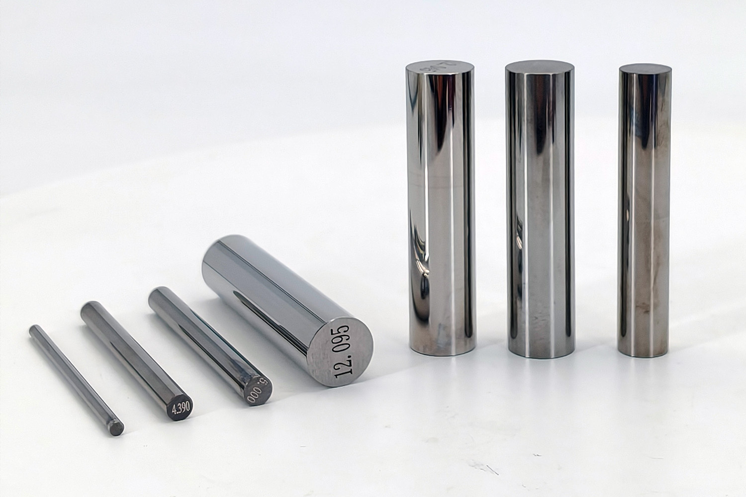
The precision thread gauge range includes metric, Unified, pipe and specialized thread systems, along with different gauge materials and custom configurations. The page lists bearing steel, tungsten carbide and zirconia ceramic options, as well as plug and ring gauge formats. (mishute.com)
Choosing Gauge Material
Gauge material should be selected after the thread specification and gauge geometry have been confirmed.
Bearing Steel
Bearing steel is commonly used for general workshop inspection. It provides a practical balance of wear resistance, availability and cost.
It normally requires appropriate cleaning, storage and corrosion protection.
Tungsten Carbide
Tungsten carbide may be suitable for frequent inspection, abrasive materials and high-volume production.
Its high wear resistance can help reduce dimensional change over repeated inspection cycles, although it must still be protected from impact.
Zirconia Ceramic
Zirconia ceramic may be considered for corrosion-sensitive, cleanroom or non-magnetic applications.
It can reduce the need for corrosion-prevention oil, but handling and application requirements should still be discussed with the gauge supplier.
MISHUTE lists these three material categories for thread gauge production and positions them for general machining, high-volume production and clean or corrosion-sensitive applications.
Gauge Wear and Calibration Planning
A gauge that was correct when purchased may not remain correct indefinitely.
Wear risk increases with:
- Inspection frequency
- Abrasive workpiece materials
- Dirty production environments
- Excessive operator force
- Poor cleaning
- Improper storage
- Repeated impact
- Corrosion
- Frequent use near one section of the gauge
Calibration frequency should be based on risk rather than an arbitrary universal interval.
Consider:
- Daily or monthly usage volume
- Gauge material
- Thread tolerance
- Cost of accepting a nonconforming part
- Historical wear results
- Customer requirements
- Quality-system requirements
- Availability of backup gauges
A high-volume production line may require a shorter verification interval than a gauge used occasionally in a controlled toolroom.
Evaluating a Thread Gauge Supplier
The supplier should review the complete technical requirement before manufacturing.
Important capabilities include:
- Thread plug and ring gauge production
- Metric, Unified and pipe-thread support
- Internal and external tolerance classes
- Left-hand and multi-start threads
- Solid and adjustable ring gauges
- Setting plugs
- Blind-hole or restricted-access designs
- Steel, carbide and ceramic materials
- Clear permanent marking
- Factory inspection reports
- Third-party calibration options
- Custom thread-profile capability
The supplier should also question incomplete information rather than assuming the pitch, class or inspection standard.
Companies sourcing several types of precision gauges can consult a precision gauge manufacturer regarding standard thread gauges and customized inspection requirements. MISHUTE lists thread plug gauges, thread ring gauges and other dimensional inspection products among its manufacturing capabilities.
Frequently Asked Questions
How do Go/No-Go thread gauges work?
The GO member must engage the product thread according to the specified inspection procedure. The NO-GO member must not engage beyond the limit allowed by the governing standard. Both conditions are normally required for acceptance.
Which Go/No-Go gauge is used for internal threads?
A thread plug gauge is used for internal threads such as tapped holes, nuts and threaded inserts.
Which Go/No-Go gauge is used for external threads?
A thread ring gauge is used for external threads on bolts, studs, shafts and male fittings.
Should a GO thread gauge pass completely?
The GO gauge should generally engage across the full required functional thread length. The exact requirement should follow the applicable thread standard and inspection procedure.
Can a NO-GO thread gauge enter the thread?
Limited initial engagement may be permitted. The allowed amount depends on the thread system, gauge type and governing standard, so one universal turn count should not be applied to every thread.
What does it mean when both GO and NO-GO gauges pass?
The thread may be outside the opposing acceptance limit and functionally too loose. The part should be quarantined and evaluated against the applicable standard.
What if neither the GO nor NO-GO gauge passes?
Possible causes include excessive material, an incorrect pitch, damaged threads, burrs, debris, gauge mismatch or alignment error. Clean and verify the setup before adjusting the machining process.
Do Go/No-Go thread gauges measure the actual pitch diameter?
No. They provide a fixed-limit pass/fail result. A thread micrometer, three-wire method, indicating gauge or other measurement system is needed when an actual numerical value is required.
Can one Go/No-Go gauge inspect different thread classes?
Normally, no. The gauge must match the thread system, size, pitch, internal or external class and thread direction specified on the drawing.
How often should Go/No-Go thread gauges be calibrated?
Calibration frequency should reflect usage, material, wear history, tolerance risk, customer requirements and the cost of an incorrect inspection result. There is no single interval suitable for every production environment.
Conclusion
Go/No-Go thread gauges reduce a complex thread geometry to a practical two-part acceptance decision.
The GO member confirms that the thread does not contain excessive material or cumulative error that prevents functional engagement. The NO-GO member helps confirm that the thread has not crossed the opposing limit and become excessively loose.
For a valid fixed-limit inspection, the GO gauge should pass as specified and the NO-GO gauge should remain within its permitted engagement limit.
Use a thread plug gauge for internal threads and a thread ring gauge for external threads. Before ordering, confirm the complete thread designation, tolerance class, direction, standard, gauging length, coating condition, material and documentation requirements.
Buyers can review GO/NO-GO thread gauge solutions for standard and customized internal or external thread inspection.