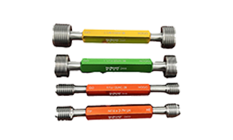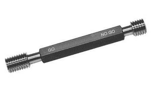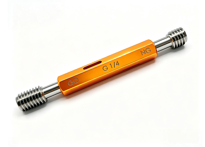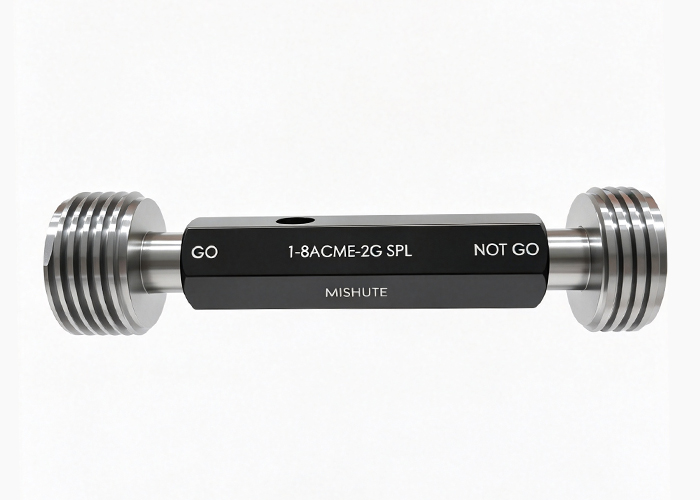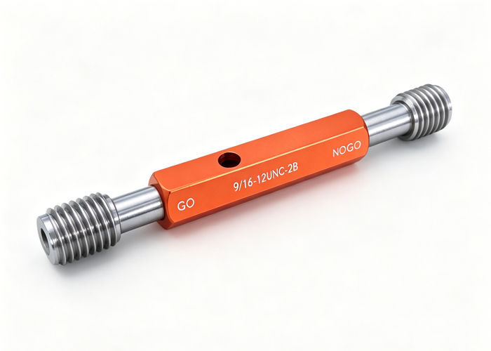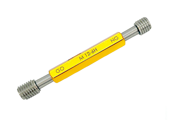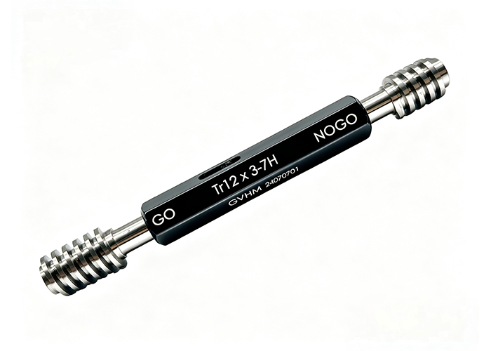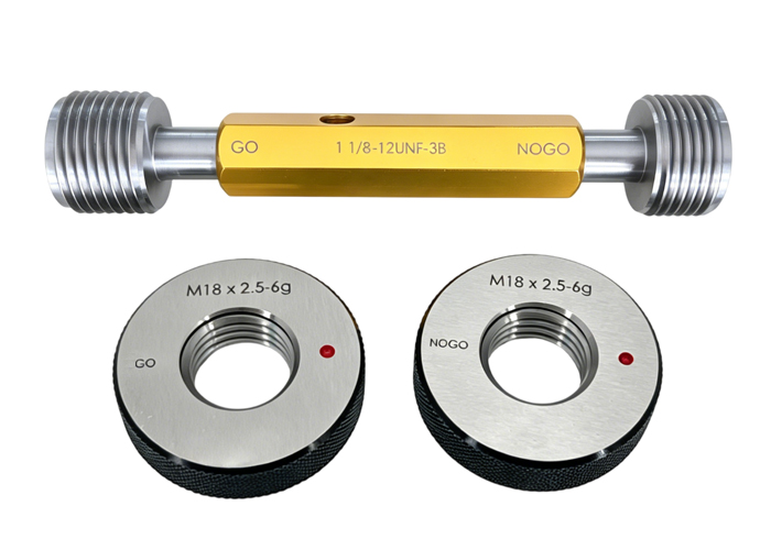
When threaded components undergo surface finishing—such as electroplating, phosphating, or galvanizing—standard inspection methods often fail if the coating thickness is ignored during initial machining. Measuring plated threads requires selecting the right inspection tool for the correct stage of manufacturing.
Using standard thread gauges to inspect uncoated parts without accounting for the dimensional effects of subsequent coating can lead to nonconformance after plating. Selecting the appropriate inspection method and establishing suitable pre-coating dimensional allowances help ensure that the finished threads meet their specified limits. Choosing between pre-plate vs post-plate thread gauges depends on two primary factors: the stage of production (machining vs. final quality control) and the coating thickness allowance on the thread flanks.
This guide details how thread geometry magnifies coating thickness, explains the engineering differences between pre-plate and post-plate gauges, outlines a step-by-step sizing framework, and highlights common shop-floor measurement pitfalls.

The Cost of the Plating Trap in Precision Threads
A common failure in precision fastener manufacturing and CNC threading occurs when parts pass inspection off the lathe, only to fail thread gauge verification after returning from the plating line. External threads bind on mating parts, internal tapped holes reject GO plug gauges, and entire batches face costly stripping or scrap.
This breakdown occurs because standard thread inspection relies on standard limits (such as Class 6H for metric internal threads or Class 2A/2B for UN series). When a standard thread plug or ring gauge is used before plating, it verifies dimensions intended for the finished, functional component. Any added surface material directly reduces clearance.
To maintain dimensional control throughout manufacturing, a two-stage inspection strategy is often appropriate:
Pre-coating inspection: Verify that the machined thread dimensions provide the required allowance for the specified coating thickness and process variation. This may involve dedicated pre-coating thread gauges or other suitable measurement methods.
Post-coating inspection: Verify that the finished thread meets the applicable drawing requirements, including any specified dimensional limits and functional thread-gauging requirements.
The inspection method and acceptance criteria should be established according to the applicable thread standard, product drawing, coating specification, and customer requirements.
Using calibrated standard thread gauges at the wrong phase creates an expensive false sense of security. Reliable quality control requires treating pre-plate dimensions as distinct manufacturing tolerances rather than relying on educated guesswork.
The Geometry of Thread Coating: Why Plating Thickness is Multiplied
Coating deposition on a thread does not result in a simple 1:1 dimensional change on the pitch diameter. Because standard thread forms feature angled flanks, coating thickness builds perpendicular to those flanks, resulting in a geometric magnification on the thread’s pitch diameter.
For standard 60-degree threads (such as ISO Metric and Unified National series), the mathematical derivation and resulting diameter shift are structured as follows:
| Geometric Parameter | Derivation / Formula | Operational Meaning |
| Thread Flank Angle | Half-angle $\alpha = 30^\circ$ | The flank lies at $30^\circ$ relative to the radial centerline. |
| Trigonometric Factor | $1 / \sin(30^\circ) = 2.0$ | Radial displacement per side equals coating thickness divided by $\sin(30^\circ)$. |
| Diametrical Calculation | $\text{Pitch Diameter Change} = \frac{2 \times \text{Coating Thickness}}{\sin(30^\circ)}$ | Both opposing flanks contribute equally across the full diameter. |
| Standard Simplified Rule | $\mathbf{\Delta PD = 4 \times \text{Coating Thickness}}$ | Every 1 µm of uniform plating creates a 4 µm shift on the pitch diameter. |
External Threads (Screws, Bolts, Studs): A uniform plating layer of 5 microns ($0.005\text{ mm}$) increases the pitch diameter by approximately 20 microns ($0.020\text{ mm}$).
Internal Threads (Nuts, Tapped Holes): That same 5-micron layer reduces the pitch diameter by 20 microns ($0.020\text{ mm}$), closing the clearance hole.
| Surface Treatment Process | Typical Thickness Range | Approximate Pitch Diameter Shift (4×) | Impact on Pre-Machining Sizing |
| Flash Chrome / Thin Gold | 1–3 µm | 4–12 µm | Minimal; standard class fits may absorb lower limits. |
| Electroplated Zinc / Nickel | 5–12 µm | 20–48 µm | Moderate to High; mandatory pre-plate gauge allowance. |
| Electroless Nickel (ENP) | 10–25 µm | 40–100 µm | High; highly uniform, requires dedicated pre-plate gauges. |
| Heavy Phosphate / Cadmium | 5–15 µm | 20–60 µm | Moderate to High; requires strict allowance calculation. |
| Hot-Dip Galvanizing | 40–100+ µm | 160–400+ µm | Extreme; requires specialized undertapping or overcutting. |
Note: The exact coating thickness and process tolerances must be verified directly with the finishing vendor, as tank agitation, current density, and part geometry can influence local deposition rates.
Pre-Plate vs. Post-Plate Thread Gauges: Technical Differences Explained
Understanding how thread inspection tools accommodate this geometric shift is critical when choosing between pre-plate and post-plate systems.
EXTERNAL THREAD (Screw) INTERNAL THREAD (Nut)
[Pre-Plate Machining Target] [Post-Plate Finished Target]
│ │
│ (Plating Layer Builds Up) │ (Plating Layer Closes In)
▼ ▼
[Post-Plate Finished Target] [Pre-Plate Machining Target]
What is a Pre-Plate Thread Gauge?
A pre-plate thread gauge is manufactured to non-standard, custom pitch diameter limits specifically calculated to account for anticipated coating thickness.
For external threads, a pre-plate thread ring gauge checks that the unplated thread is machined undersize relative to the final class of fit.
For internal threads, a pre-plate thread plug gauge checks that the unplated tapped hole is machined oversize relative to the final class of fit.
What is a Post-Plate Thread Gauge?
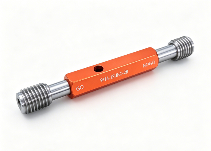
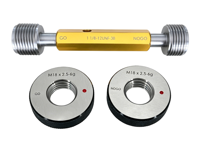
A post-plate thread gauge is simply a standard class-of-fit gauge (e.g., 6H, 6g, 2B, or 2A). It checks the finished, fully treated component to ensure that the assembly meets the final engineering drawing specifications.
| Feature / Criterion | Pre-Plate Thread Gauges | Post-Plate Thread Gauges |
| Primary Inspection Stage | In-process CNC turning, milling, and tapping | Final QA, incoming goods, and assembly inspection |
| Pitch Diameter Limits | Custom offset (Undersize for screws; Oversize for nuts) | Standard nominal tolerance band (e.g., 6H, 2A) |
| External Thread GO/NOGO | Lower pitch diameter boundary than final print | Final design limits per standard thread tables |
| Internal Thread GO/NOGO | Higher pitch diameter boundary than final print | Final design limits per standard thread tables |
| Tool Marking | Often etched with “PRE-PLATE” and exact PD values | Standard size, pitch, and tolerance class (e.g., M10x1.5-6H) |
| Standard Availability | Frequently made-to-order based on plating spec | Off-the-shelf catalog standards |
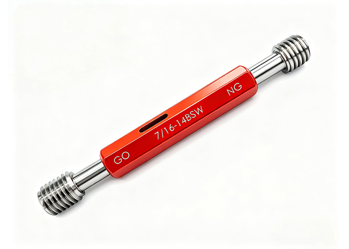
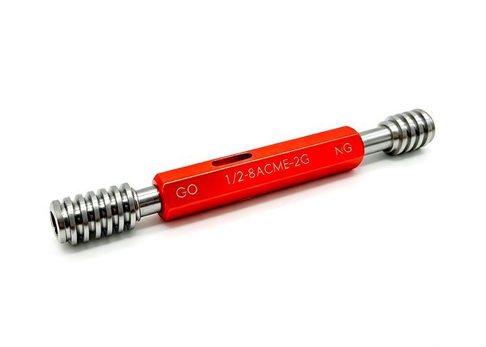
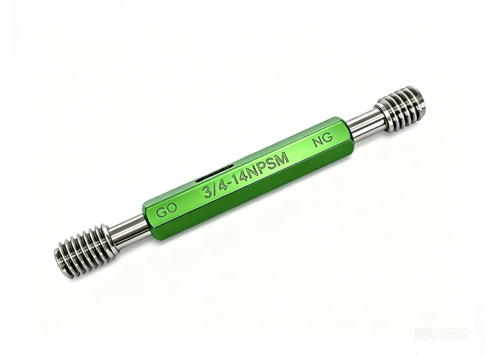
For tight-tolerance applications, selecting dedicated pre-plate thread plug gauges provides a direct physical check on the machine floor before parts leave for finishing.
How to Select the Right Pre-Plate Gauges: A 4-Step Engineering Framework
Setting up inspection for plated threads requires clear coordination between the design drawing, the machine shop, and the plating facility.
Step 1: Extract Plating Thickness Range (Min & Max)
│
▼
Step 2: Calculate Pitch Diameter Allowances (4x Rule)
│
▼
Step 3: Evaluate Standard Classes vs. Custom PD Limits
│
▼
Step 4: Establish GO and NOGO Sizing Boundaries
Step 1: Extract Plating Thickness Range from the Drawing
Do not rely on a single nominal plating dimension. Review the technical specification to find the minimum and maximum allowable coating thickness ($T_{\min}$ and $T_{\max}$).
Step 2: Calculate Pitch Diameter Allowances
Apply the 4x multiplier to establish the total diametrical shift on the 60° thread flanks:
Minimum Pitch Diameter Shift: $\Delta PD_{\min} = 4 \times T_{\min}$
Maximum Pitch Diameter Shift: $\Delta PD_{\max} = 4 \times T_{\max}$
For external threads, your pre-plate machining window must drop below the standard maximum envelope by at least $\Delta PD_{\max}$. For internal threads, your pre-plate machining window must expand above the standard minimum envelope by at least $\Delta PD_{\max}$.
Step 3: Evaluate Standard Class Offsets vs. Custom Pitch Diameters
Before ordering custom tooling, verify whether an existing standard tolerance class provides the required allowance:
In metric external threads, moving from class 6g to 6e or 6f introduces a fundamental deviation (an intentional air gap) that may absorb thin coatings (under 5 µm).
For heavy coatings (over 8–10 µm) or tight tolerance classes, standard deviations are rarely sufficient or balanced. In these situations, procuring custom thread gauges ground to exact pre-plate pitch diameter boundaries is the most reliable approach.
Step 4: Establish GO and NOGO Boundaries
A common mistake is shifting only the GO limit. Both the GO (maximum material condition) and NOGO (least material condition) limits must shift together:
Pre-Plate Internal Thread Plug Gauge:
$\text{GO PD} = \text{Standard GO PD} + \Delta PD_{\max}$
$\text{NOGO PD} = \text{Standard NOGO PD} + \Delta PD_{\min}$
Pre-Plate External Thread Ring Gauge:
$\text{GO PD} = \text{Standard GO PD} – \Delta PD_{\max}$
$\text{NOGO PD} = \text{Standard NOGO PD} – \Delta PD_{\min}$
Common Workshop Pitfalls When Inspecting Coated Threads
Even with correctly calculated pre-plate tooling, thread verification can produce false rejections or undetected defects if shop-floor variables are not monitored.
1. The “Dog-Bone” Effect (Edge Buildup)
In electroplating processes, electrical current concentrates at sharp corners and external edges. The crests of external threads and the lead-in threads of fasteners receive higher current density, resulting in heavier deposit thickness than on the root or middle flanks.
If a post-plate GO ring gauge binds on the first two threads, inspect the entry chamfer under magnification before concluding the pitch diameter is oversized. Chamfering thread ends cleanly before plating reduces localized electrical concentration.
2. Blind Hole Solution Trapping and Uneven Internal Plating
Internal threads present distinct electroplating challenges because the interior of a hole acts as a low-current-density area (Faraday cage effect). While the entrance of the tapped hole may build up plating thickness, the deeper threads may receive almost none.
When inspecting long threaded holes with a post-plate GO plug gauge, binding at the hole entrance combined with a loose fit at the bottom points to non-uniform deposition rather than an incorrect pre-plate machining diameter. In such cases, electroless nickel or specialized internal auxiliary anodes may be required.
3. Measuring Worn Gauges
Gauges used in high-volume machining environments experience abrasive wear. When working with micro-inch or micron-level plating allowances, a worn GO plug gauge can accept tapped holes that are undersized. Establishing strict calibration cycles with master setting plugs protects against undetected tool wear.
Conclusion: Balancing Shop-Floor Quality and Final Acceptance
Reliable production of plated threaded parts requires matching the inspection tool to the manufacturing phase. Relying exclusively on standard post-plate gauges leads to post-plating sorting, unplanned reworking, and scrap.
By applying the 4x pitch diameter rule, calculating proper flank allowances, and deploying dedicated pre-plate gauges for machining verification alongside post-plate gauges for final QA, manufacturers can maintain consistent dimensional control through every finishing step.
Key Takeaways
The 4x Geometry Rule: For 60-degree Metric and UN threads, coating thickness increases the pitch diameter of external threads—and reduces that of internal threads—by roughly four times the single-side plating thickness ($\Delta PD = 4 \times T$).
Two Distinct Tools: Pre-plate gauges verify adjusted dimensions during machining; post-plate gauges confirm standard design conformance after surface treatment.
Shift Both Limits: When calculating pre-plate gauge limits, shift both GO and NOGO limits using maximum and minimum plating thicknesses to preserve a valid tolerance window.
Process Variations: Watch for non-uniform deposition, such as edge buildup (“dog-bone effect”) on external lead threads and current starvation inside deep internal threads.
Frequently Asked Questions (FAQ)
Can I use a looser standard tolerance class (such as 6G instead of 6H) as a pre-plate gauge?
In some light-coating scenarios, a standard class with fundamental deviation (such as class G for internal threads or class e/f for external threads) provides enough clearance for thin flash plating (1–3 µm). However, standard tolerance steps rarely match the precise minimum and maximum plating requirements of industrial electroplating, making dedicated pre-plate gauges the safer choice for coatings exceeding 5 µm.
Do pre-plate thread gauges have special markings?
Yes. Proper industrial practice requires pre-plate thread plug and ring gauges to be etched with “PRE-PLATE” alongside the nominal size, the specific modified pitch diameter limits, and the serial number to prevent operators from confusing them with standard finishing gauges.
How does anodizing affect internal thread gauge selection compared to electroplating?
Standard sulfuric acid anodizing penetrates into the base aluminum by approximately 50% of the total coating thickness while building outward by 50%. Therefore, the dimensional growth on the surface is half the total anodize layer thickness. Hardcoat anodizing creates substantial growth and demands careful pre-plate thread calculation, whereas standard decorative anodizing creates minimal dimensional change.
What technical details must be provided when ordering custom pre-plate gauges?
When procuring custom pre-plate gauges, provide the nominal thread size and pitch, the final tolerance class (e.g., M12x1.5-6H or 1/2-13 UNC-2A), the plating process specification, and the minimum and maximum coating thickness. Alternatively, provide the exact calculated pre-plate GO and NOGO pitch diameters directly to the gauge manufacturer.