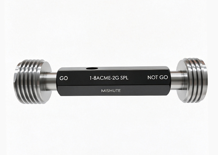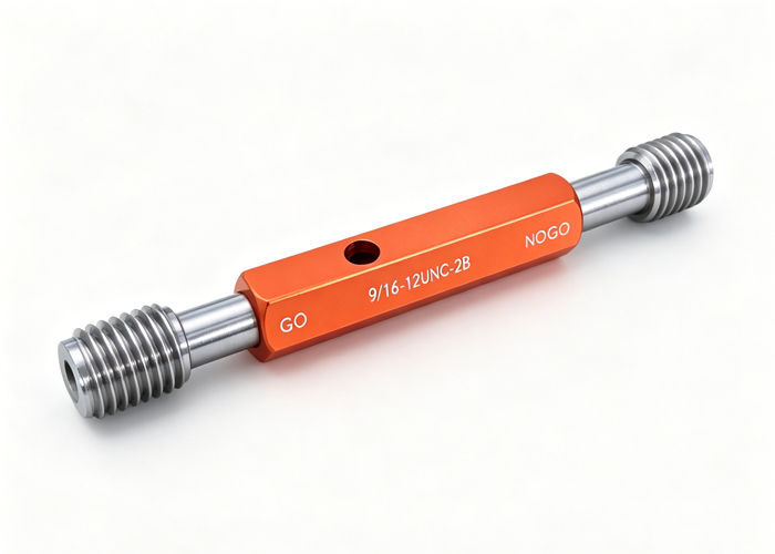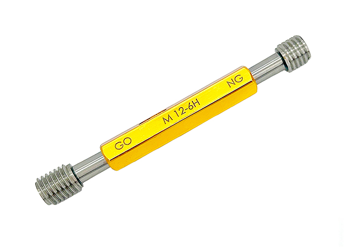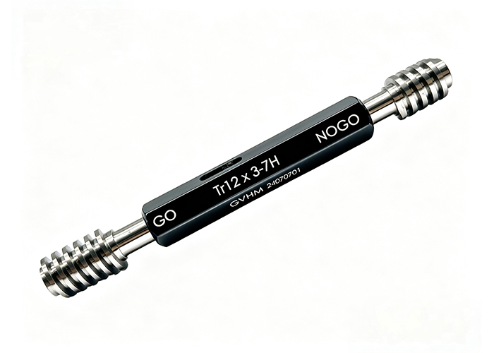
Thread gauge calibration frequency typically defaults to an interval of 6 to 12 months in standard manufacturing environments, but fixed calendar dates rarely reflect actual operational wear. A machine shop threading abrasive cast iron on three shifts will wear down a pitch diameter in weeks, whereas a climate-controlled calibration laboratory using master gauges once a month can safely maintain a multi-year cycle. Determining the correct interval requires balancing production throughput, workpiece material hardness, tolerance grade, and historical inspection data.
This guide outlines baseline recalibration schedules, the variables that accelerate physical tool wear, the procedural differences between in-house verification and accredited laboratory recertification, and practical end-of-life criteria for fixed-limit gauging tools.
Why Thread Gauge Calibration Frequency Directly Impacts Machining Profitability
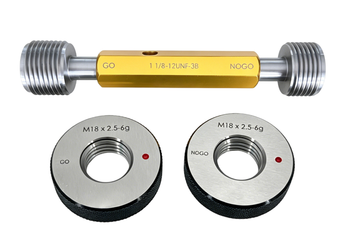
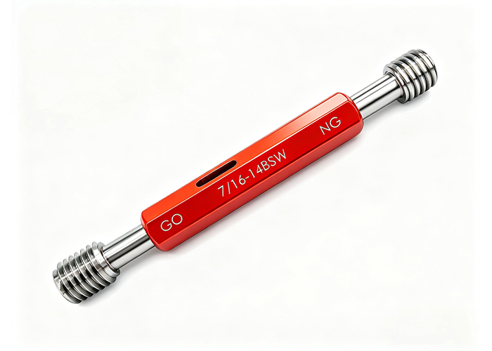
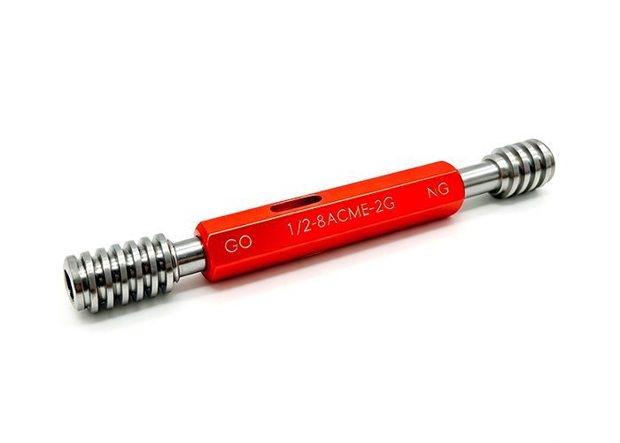
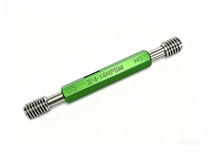
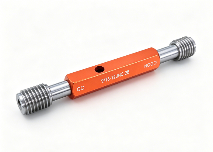
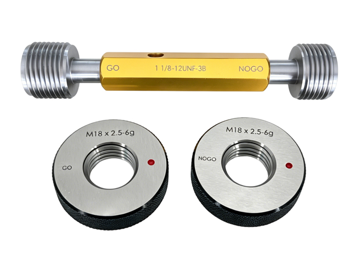
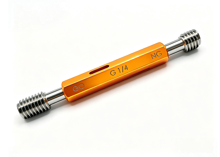
Fixed-limit thread gauges—specifically Go and No-Go plugs and rings—operate through direct physical contact. Every engagement against an internal or external thread removes microscopic layers of steel through sliding friction.
| Progression Stage | Physical Mechanism | Direct Measurement Impact | Manufacturing Consequence |
| Stage 1: Pristine State | Factory-certified new tool | Within nominal design tolerance | Accurate component sorting |
| Stage 2: Operational Friction | Continuous metal-to-metal rubbing | Flank erosion and crest rounding | Gradual baseline calibration drift |
| Stage 3: Tolerance Breach (Go Plug) | Cumulative flank wear | Pitch diameter shrinks below lower limit | Rejects compliant parts (False Scrap) |
| Stage 4: Tolerance Breach (No-Go) | Crest and clearance wear | Effective limit opens beyond threshold | Accepts out-of-spec parts (Customer Returns) |
When a Go thread plug gauge wears below its minimum wear limit, it begins rejecting parts that are actually within drawing tolerance, driving up false scrap rates and unnecessary machine downtime. Conversely, if a No-Go thread ring gauge wears beyond its allowable limit, it allows oversized or undersized threads to pass downstream to assembly lines or end customers. Implementing a calculated calibration frequency prevents these silent measurement errors from compromising delivery schedules and supplier quality audits.
How Often Should You Calibrate Thread Gauges? (Standard Baselines)
Most quality management systems compliant with ISO 9001 or IATF 16949 establish an arbitrary 12-month baseline for newly commissioned measuring equipment. While 12 months provides an administrative starting point, baseline intervals should be calibrated according to operating intensity:
| Operating Environment | Typical Usage Intensity | Recommended Calibration Interval | Primary Failure Mode |
| High-Volume CNC Production Line | > 200 parts inspected per shift | 1 to 3 Months | Abrasive wear on Go member crests |
| Batch Machining / General Job Shop | 20 to 50 parts inspected per day | 6 Months | Gradual pitch diameter erosion |
| Final Quality Inspection (QA Lab) | Sampling inspection only | 12 Months | Localized flank nicking or burrs |
| Master Setting Reference Gauges | Used only to set adjustable rings | 24 to 36 Months | Environmental corrosion or storage damage |
When deploying new precision thread gauges on a production line without historical wear metrics, set the initial calibration check at 3 months. If the pitch diameter demonstrates zero measurable drift during that evaluation, extend the interval incrementally to 6 or 12 months.
5 Critical Variables That Alter Your Recertification Schedule
A static calendar schedule fails when operating variables shift. Quality engineers should adjust recalibration intervals based on five measurable factory conditions:
1. Workpiece Material Hardness and Abrasiveness
Machining abrasive materials such as cast iron, titanium alloys, hardened tool steels, or unwashed cast aluminum accelerates contact abrasion. In contrast, checking brass, mild steel, or plastics extends gauge functional life significantly.
2. Operating Environment and Part Cleanliness
Residual chips, abrasive grinding swarf, and contaminated coolant acting as lapping compounds inside threaded holes degrade gauge flanks. Gauges used directly at machine tools require recalibration up to three times more frequently than those used in cleanroom inspection stations.
3. Gauge Member Type (Go vs. No-Go)
Go gauges enter every acceptable threaded hole over its entire engagement length, bearing virtually all frictional travel. No-Go gauges enter only when a part is out of specification, experiencing negligible wear. Consequently, Go members often require recertification or replacement two to three times more often than companion No-Go members.
4. Component Tolerance Tightness
Checking Class 4H/6H or Class 3B threads leaves minimal gauge tolerance band margin before wear pushes the tool out of compliance. Coarser thread classes permit wider gauge wear allowances, supporting longer calibration intervals.
5. Operator Technique and Gauge Construction
Manual cross-threading, excessive insertion torque, or dropping gauges on concrete floors instantly alters pitch geometry. Shops utilizing wear-resistant hardened steel thread gauges maintain calibration consistency longer than those utilizing soft, untreated carbon steel tooling.
In-House Daily Check vs. Accredited Recertification: What Is the Difference?
A common quality control error is confusing daily functional verification with metrological calibration. Both procedures are required to maintain traceability:
| Comparison Attribute | In-House Daily Verification | Accredited Metrological Recertification |
| Primary Objective | Immediate operational screening | Full dimensional traceability & compliance |
| Inspection Frequency | Daily, per shift, or weekly | 3, 6, 12, or 24 months (schedule-based) |
| Operating Location | Production floor or shop tool crib | Environment-controlled metrology lab (20°C / 68°F) |
| Equipment Deployed | Truncated setting plugs, 10x optical loupe | Three-wire bench micrometers, UMMs, roundness testers |
| Parameters Evaluated | Functional engagement, clearance, visible damage | Pitch diameter, flank angles, lead error, taper |
| Documentation Issued | Internal log sheet / pass-fail check-off | Traceable Certificate of Calibration with uncertainty data |
| Regulatory Authority | In-house operators or floor quality inspectors | ISO/IEC 17025 accredited laboratory technicians |
In-House Verification (Daily/Weekly): Conducted at the workstation by inspectors or machinists. For thread rings, this involves testing resistance against a calibrated truncated setting plug gauge. For thread plugs, it includes visual inspection under magnification for chips, nicks, or thread root fouling. No calibration certificate is issued; the result is recorded as a pass/fail log entry.
Accredited Recertification (Scheduled Interval): Conducted in an environmentally controlled metrology lab (operating at 20°C / 68°F). Technicians measure absolute dimensional attributes—including pitch diameter, major/minor diameters, lead pitch error, and included flank angles—using traceable three-wire systems, optical comparators, or universal measuring machines. This process results in a formal Certificate of Calibration documenting traceable uncertainties.
Step-by-Step Process: How to Re-Certify Your Thread Gauges Properly
Executing a defensible recertification cycle requires adherence to a standardized sequence:
Step 1: Pre-Cleaning and Degreasing
Submerge the gauge in an industrial solvent to dissolve dried machining oils, coolant salts, and particulate swarf. Ultrasonic cleaning is recommended for fine-pitch thread ring gauges. Dry thoroughly using clean, dry compressed air or lint-free wipes.
Step 2: Visual and Tactile Triage
Inspect the lead threads under minimum 10x optical magnification. If burrs, severe drop gouges, or flaking chrome/carbide layers are present, retire the gauge immediately. Measuring an outwardly damaged tool wastes lab resources.
Step 3: Temperature Stabilization
Transfer the cleaned gauge to a temperature-controlled calibration environment maintained at 20°C (±1°C). Allow the tool to soak for a minimum of 4 to 12 hours (depending on mass) to normalize thermal expansion before taking readings.
Step 4: Pitch Diameter and Geometry Measurement
Thread Plugs: Measure the pitch diameter using calibrated thread measuring wires (the three-wire method) and an indicator bench micrometer, applying measuring forces specified by standard standards (e.g., ASME B1.2 or ISO 1502). Inspect lead error and half-angle deviation.
Thread Rings: Inspect wear limits utilizing a calibrated truncated Go/No-Go setting plug gauge, or measure directly using an internal diameter measuring machine equipped with spherical styli.
Step 5: Uncertainty Assessment and Certification
Compare observed dimensions against allowable manufacturing limits and wear allowances. If all parameters fall within tolerance, issue an updated calibration sticker and certificate documenting serial numbers, environmental conditions, standard references, and date of next calibration.
Repair or Replace? Determining When a Thread Gauge Reaches End-of-Life
When an inspection reveals that a thread gauge has drifted out of tolerance, shops must evaluate economic and technical viability between rework and replacement:
| Observed Gauge Condition | Tool Type | Recommended Course of Action | Decision Rationale |
| Go Ring Gauge Loose on Setting Plug | Adjustable Thread Ring | Recondition / Reset | Turn adjustment screw, reseal with wax, and re-certify to setting plug. |
| Go Ring Gauge Worn Beyond Limit | Solid (Non-Adjustable) Ring | Replace Tool | Internal grinding or lapping back into spec is economically unfeasible. |
| Go Plug Pitch Diameter Undersized | Taperlock / Trilock Plug | Replace Member | Once the core steel wears below minimum pitch limit, it cannot be safely built up. |
| Localized Nicks on Lead Chamfer | Thread Plug or Ring | Minor Dressing | Stone lead threads carefully to clear raised metal, provided pitch flanks are untouched. |
| Flank Pitting or Deep Corrosion | Any Thread Gauge | Replace Tool | Corrosion creates dimensional instability and accelerates part galling. |
When physical reconditioning costs approach 50% of the replacement price—or when turnaround downtime disrupts machining schedules—it is more economical to replace worn thread gauges with factory-certified new units.
Key Takeaways
Calibration intervals are risk-dependent: Establish a 12-month baseline, but shorten cycles to 1 to 3 months for high-volume automated lines or abrasive workpiece materials.
Go members fail first: Allocate more testing bandwidth to Go plugs and rings, which incur continuous frictional wear, whereas No-Go members rarely experience significant dimension changes.
Verification is not calibration: Daily checks against setting plugs detect immediate damage, but they do not replace comprehensive multi-parameter lab recertification.
Retire non-adjustable worn tools: Solid thread rings and worn plug members should be replaced once they breach wear limits; manual field modifications compromise inspection integrity.
Frequently Asked Questions About Thread Gauge Maintenance
Can we calibrate thread ring gauges without a setting plug?
Thread ring gauges are most efficiently inspected using calibrated truncated setting plug gauges. While direct measurement using universal measuring machines (UMMs) equipped with small-diameter ball probes is possible, it requires specialized metrology software and extended setup times. For general manufacturing facilities, paired setting master plugs remain the industry standard.
How should thread gauges be stored to prevent calibration drift?
Store gauges in a dedicated, humidity-controlled tool crib away from coolant mists and temperature fluctuations. Clean them after every shift, coat threads with an acid-free corrosion-preventative oil or microcrystalline wax, and store them flat in partitioned wooden or molded polymer trays rather than stacked loose in metal bins.
Does dropping a thread gauge automatically void its calibration certificate?
Yes. Impact against hard surfaces frequently induces micro-fractures, burrs lead threads, or shifts internal stresses, immediately voiding calibration validity. Any dropped gauge must be quarantined and submitted for dimensional and visual verification before returning to the production line.
Ensure Measurement Accuracy with Certified Thread Gauges
Preventing non-conforming threaded components requires robust inspection discipline backed by dependable gauging standards. When routine recertification confirms that your tooling has reached its wear limit, sourcing dimensionally stable replacements minimizes downtime risk.
Explore Mihe’s catalog of precision-machined thread gauges to review standardized plug and ring sizes, or submit your specific thread class, pitch, and material requirements to our technical team for custom gauging evaluations.