Thread mismatches cause fluid leaks, damaged mating components, assembly line shutdowns, and rejected export shipments. The three primary global thread standards—Metric (ISO), Unified National (UNC/UNF), and Pipe standards (NPT/BSPT)—differ fundamentally in flank angle, pitch definition, taper, and sealing mechanisms.
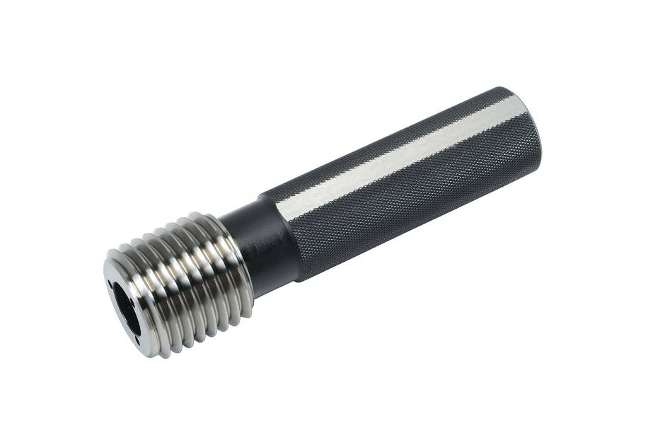
Verifying thread compatibility requires understanding these geometry variations and applying calibrated thread gauges during machining and incoming quality control. This guide examines the engineering distinctions between major international thread profiles, clarifies why parallel and tapered threads cannot interchange, and outlines how quality teams use Go/No-Go plug and ring gauges to prevent assembly failures.
1. The Cost of Thread Incompatibility: Why Global Standards Matter in Precision Manufacturing
Thread compatibility issues rarely stem from machining errors alone; more often, they originate from subtle geometry mismatches across regional standards. Fasteners or fluid ports that appear visually identical often possess incompatible thread forms, lead angles, or flank profiles.
| Stage | Progression Phase | Physical Impact on Thread Interface | Operational Risk |
| Stage 1 | Initial Assembly | Forcing incompatible thread pitches or profiles together | Increased insertion torque and point-loading |
| Stage 2 | Mechanical Deformation | Truncated crest shearing and root gouging | Severe metal loss and flank surface scoring |
| Stage 3 | Material Binding | Galling, micro-welding, and cross-threading | Permanent seizure of mating components |
| Stage 4 | Field Operation | Continuous spiral leakage and mechanical separation | Joint blow-off under operating fluid pressure |
When an unverified male fitting is forced into an incompatible female port:
Flank contact is compromised: Instead of uniform load distribution across mating flank angles, stress concentrates on point contacts at the crest or root.
Galling and cold-welding occur: Mismatched leads cause rapid thread binding during torquing, especially in stainless steel and aluminum alloys.
Hydrostatic sealing fails: Tapered pipe fittings with divergent thread angles create spiral leak paths that thread sealants and PTFE tape cannot seal under operating pressures.
Scrap rates increase: Mismatched parts pass casual visual inspection but seize during final assembly, forcing the teardown of completed assemblies.
Implementing standard-specific thread gauges at receiving and production stages stops out-of-tolerance and cross-standard parts before they enter the assembly stream.
2. Core Differences at a Glance: Flank Angle, Pitch, and Sealing Mechanisms
Thread systems divide into two primary functional categories: mechanical fastening threads (straight/parallel) and fluid transmission threads (straight or tapered).
| Parameter | Metric (ISO) | Unified National (UNC/UNF) | NPT (National Pipe Taper) | BSPT (British Standard Pipe Taper) |
| Standard Specification | ISO 1502 | ASME B1 | ASME B1.20.1 | ISO 7-1, BS 21, EN 10226-1 |
| Thread Form Type | Parallel (Straight) | Parallel (Straight) | Tapered (1:16 on diameter) | Tapered (1:16 on diameter) |
| Flank Angle | 60° (Symmetrical) | 60° (Symmetrical) | 60° (Symmetrical) | 55° (Whitworth form) |
| Pitch Designation | Millimeters (distance crest-to-crest) | Threads Per Inch (TPI) | Threads Per Inch (TPI) | Threads Per Inch (TPI) |
| Crest / Root Design | Flat crests, rounded roots | Flat/rounded crests, rounded roots | Flat crests and roots (truncated) | Rounded crests and roots |
| Primary Sealing Method | Mechanical clamp + O-ring/washer | Mechanical clamp + O-ring/gasket | Thread interference + sealant (or dryseal on NPTF) | Thread flank interference + sealant |
| Applicable Inspection Gauges | Go/No-Go parallel plug & ring gauges | Go/No-Go parallel plug & ring gauges | L1, L2, L3 taper step/limit gauges | Taper plug & ring step gauges |
Understanding these distinctions is essential across industrial piping, pneumatic manifolds, and downstream components produced by plastic and metal extrusion-line systems, where extruded conduits interface with threaded metal fittings, pressure sensors, and valves.
3. Parallel Mechanical Fasteners: Metric (ISO) vs. Unified (UN/UNF)
Metric and Unified standards represent the vast majority of structural and mechanical fastening. Both employ a 60° symmetrical flank angle, which frequently leads operators to mistake them for interchangeable profiles. They are not.
| Standard Category | Pitch Calculation & Unit | Representative Example | Axial Pitch Metric Equivalent | Intermateability Consequence |
| Metric (ISO) | Direct linear distance (mm) | M10 × 1.5 | 1.500 mm | Cumulative lead mismatch of 0.0875 mm/turn causes binding and thread stripping after 3–4 turns |
| Unified (UN/UNF) | 1 / TPI (Fractional inches) | 3/8″-16 UNC (16 TPI) | 1.5875 mm (1/16″) |
3.1 Metric ISO (M): Understanding Pitch and Tolerance Positions
Metric fasteners are designated by nominal diameter followed by pitch (for example, M12 × 1.75 coarse or M12 × 1.25 fine). Coarse pitches are standard; fine pitches provide higher tensile stress areas and greater resistance to vibrational loosening.
Metric tolerances use alphanumeric designators to specify allowance and tolerance grade:
Internal Threads (Nuts/Tapped Holes): Designated by uppercase letters (e.g., 6H, 7H). The number represents the tolerance grade, while the letter denotes position (H has zero fundamental allowance).
External Threads (Bolts/Studs): Designated by lowercase letters (e.g., 6g, 6e). The letter denotes allowance (g provides clearance for plating or coatings).
Fit Classes: 6H/6g represents the universal commercial standard. Tighter fits (e.g., 4H/4h) are specified for precision instrumentation, requiring dedicated metric thread plug and ring gauges to prevent false acceptances.
3.2 Unified National (UNC/UNF): TPI and Fit Classes
The Unified Thread Standard defines nominal size in fractional inches or wire gauge numbers, combined with the thread count per axial inch (TPI):
UNC (Coarse Thread): Standard for bulk manufacturing and soft materials (aluminum, cast iron, plastics) requiring rapid assembly and resistance to stripping.
UNF (Fine Thread): Delivers higher core tensile strength and finer adjustment resolution, common in aerospace and automotive assemblies.
Unified tolerances use numbered classes followed by letters:
Class 1A / 1B: Loose fit for dirty or rapidly assembled field environments.
Class 2A / 2B: The industrial standard for general commercial bolts and nuts (2A external, 2B internal).
Class 3A / 3B: Close-tolerance fit without allowance, specified for high-stress aerospace and military assemblies.
3.3 Can Metric and UN Threads Intermix?
Metric and Unified threads cannot interchange. While certain pairs have nearly identical nominal outside diameters (such as M8 × 1.25 OD of 8.00 mm vs. 5/16″-20 UNF OD of 7.94 mm), their pitches diverge. An M8 × 1.25 thread has a pitch of 1.250 mm, whereas 5/16″-20 has a pitch of 1.270 mm (20 TPI).
Attempting to assemble them causes initial hand-threading for 1–2 turns, followed by immediate flank jamming. Forcing the fastener strips internal threads or shears the bolt.
4. Tapered Pipe Systems: NPT vs. BSPT (Whitworth Standard)
Tapered pipe connections rely on metal-to-metal flank interference along a continuous taper to form a pressure-tight seal. Using the wrong standard in fluid, gas, or hydraulic systems presents severe safety and containment hazards.
| Tapered Standard | Flank Angle | Crest / Root Profile | Taper Rate | Intermixing Risk |
| NPT (ASME B1.20.1) | 60° | Truncated flat crest and root | 1:16 on diameter (3/4 in/ft) | Joint leaves continuous spiral gaps along crest/root; blow-out occurs under pressure |
| BSPT / ISO 7-1 (R/Rc) | 55° (Whitworth) | Rounded crest and root | 1:16 on diameter (1° 47′) | Thread flanks make point-contact only; threads gall and fail hydrostatic containment |
4.1 NPT (ASME B1.20.1): 60° Flank Angle with 1:16 Taper
National Pipe Taper (NPT) features a 60° thread angle and flat crests and roots. As the male fitting threads into the female port, the 1:16 diameter taper forces the thread flanks together. Because microscopic clearances remain between the flat crests and roots, standard NPT requires an approved thread sealant or PTFE tape to achieve a bubble-tight seal.
Note on NPTF (Dryseal): NPTF (ASME B1.20.5) modifies the crest and root truncations so that crests crush into roots during torquing, creating a mechanical seal without sealant. NPT and NPTF threads require distinct inspection gauges to verify root and crest truncation limits.
4.2 BSPT / ISO 7-1 (R/Rc): 55° Whitworth Profile
British Standard Pipe Taper (BSPT)—designated as R for external taper threads and Rc for internal taper threads under ISO 7-1—uses the 55° British Standard Whitworth profile. Its crests and roots are uniformly rounded.
The differences between NPT and BSPT cause severe mismatches:
Thread Angle Mismatch: The 5° divergence between a 60° NPT flank and a 55° BSPT flank prevents complete flank surface contact.
Pitch Mismatches: While 1/2″ and 3/4″ sizes share 14 TPI across both standards, 1/8″, 1/4″, 3/8″, and 1″ sizes differ in TPI (for example, 1″ NPT uses 11.5 TPI, whereas 1″ BSPT uses 11 TPI).
5. Industrial Quality Control: How to Select and Use Thread Gauges for Inspection
Dimensional verification of threaded features requires specialized fixed-limit metrology tools. Calipers and micrometers cannot reliably measure pitch diameter, lead error, or flank angle uniformity inside a tapped hole or across an external thread.
| Thread Type | Inspection Tool | Target Feature | Acceptance Criteria |
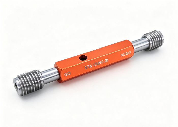
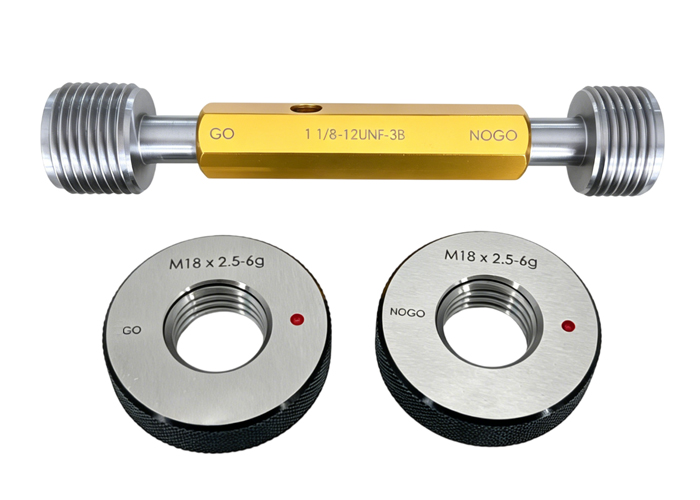
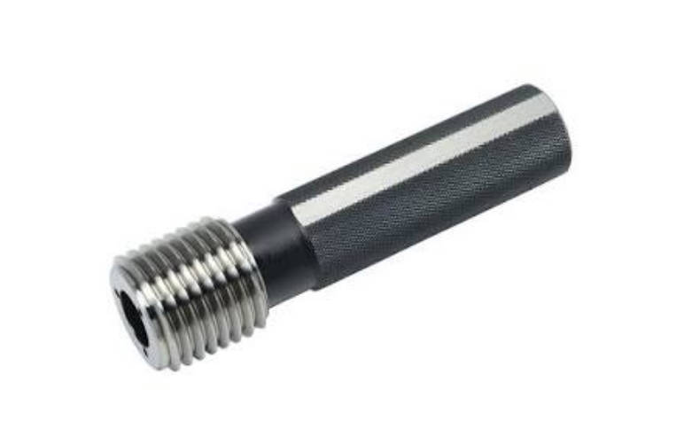
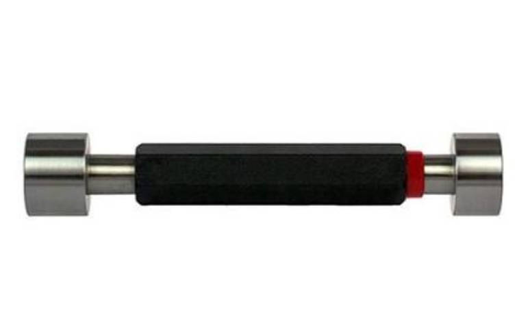
| Internal Parallel (Metric/UN) | Thread Plug Gauge (Go / No-Go) | Maximum & Least Material Conditions (MMC / LMC) | Go enters fully by hand; No-Go stops within 2–3 turns |
| External Parallel (Metric/UN) | Thread Ring Gauge (Go / No-Go) | Major & Pitch Diameter Limits | Go passes entire thread; No-Go turns ≤ 3 rotations |
| Tapered Pipe (NPT/BSPT) | Step / Notch Gauges (L1, L2, L3) | Pitch diameter standoff & effective thread length | Part end face flush within step tolerance notch (±1 turn) |
5.1 Go / No-Go Thread Plug & Ring Gauges
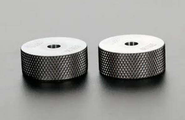
Parallel threads (Metric and UN/UNF) are evaluated using Go / No-Go fixed gauges that inspect pitch diameter limits:
Go Thread Plug / Ring Gauge: Evaluates the Maximum Material Condition (MMC). The Go member verifies that pitch diameter, lead, and flank angle do not exceed the upper limit on an external thread or fall below the lower limit on an internal thread. The Go gauge must assemble smoothly through the full length of the thread by hand, without excessive force.
No-Go Thread Plug / Ring Gauge: Evaluates the Least Material Condition (LMC). The No-Go gauge checks that the pitch diameter is not oversized on internal threads or undersized on external threads.
Acceptance Criterion: The No-Go gauge must not enter the workpiece more than two to three complete turns. Immediate entry beyond three turns indicates an out-of-tolerance pitch diameter and requires rejection.
5.2 Step-Limit Verification for Tapered Pipe Threads (L1, L2, L3)
Tapered threads do not use standard Go/No-Go parallel checks because diameter varies continuously along the axis. Instead, inspection relies on standoff gauges:
L1 Thread Plug / Ring Gauge: Checks hand-tight engagement depth. The gauge features precision ground steps (minimum, basic, maximum notch). When screwed onto or into the pipe thread hand-tight, the end face of the part must align within the step tolerance window (typically ±1 turn from the basic notch).
L2 (External) and L3 (Internal) Gauges: Used alongside L1 gauges on critical fluid connections to verify thread taper accuracy, full-thread length, and flank contact past hand-tight engagement.
5.3 Wear Allowances, Calibration, and Environmental Control
Thread inspection accuracy depends on proper gauge maintenance:
Thermal Expansion: Metrology inspection should take place near standard calibration temperatures (20°C / 68°F). Inspecting warm parts straight from CNC machining leads to false out-of-spec readings once parts cool.
Wear Limits: Go gauges sustain abrasive contact and lose material over time. Facilities must establish scheduled calibration cycles using master setting plugs to retire worn gauges before out-of-spec components pass into finished inventory.
6. Sourcing & Verification Checklist: Specifying Gauges with a Manufacturer
When procuring inspection equipment from a dedicated thread gauges manufacturer, purchasing teams must provide complete engineering definitions to avoid ordering incorrect tool blanks or tolerance classes.
| Specification Step | Engineering Parameter | Technical Requirement Example |
| 1. Standard Profile | International Thread Standard | ISO Metric, UN (ASME B1.1), NPT (ASME B1.20.1), or BSPT (ISO 7-1) |
| 2. Size & Pitch | Nominal Diameter & Lead | M16 × 1.5 (Metric pitch in mm) or 3/4″-14 (Imperial TPI) |
| 3. Tolerance Class | Internal or External Class | 6H (Internal Metric), 6g (External Metric), or Class 2B / 2A (Unified) |
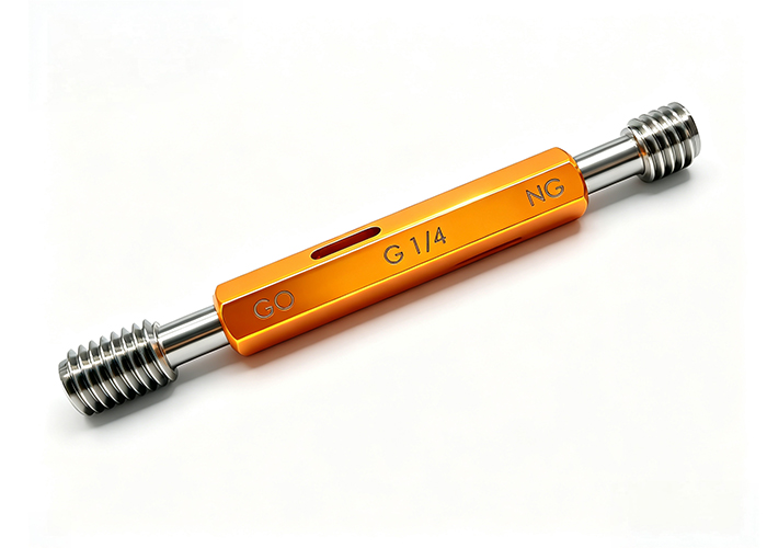
| 4. Gauge Configuration | Physical Tool Style | Double-End Plug (Go/No-Go), Single-End, or Solid/Adjustable Ring |
| 5. Material & Tooling | Substrate Hardness | Hardened Tool Steel (58–62 HRC) or Tungsten Carbide |
| 6. Wear Enhancement | Surface Coating | Chrome plating or TiN coating for automated or high-cycle inspection |
| 7. Quality Verification | Traceable Calibration | Calibration certificate verifying pitch diameter to ISO 17025 / national standards |
Key Takeaways
Flank Angle Dictates Compatibility: Metric and UN/UNF threads share a 60° angle but diverge in pitch. NPT (60°) and BSPT (55°) can never be combined, as mismatched flank angles create structural instability and fluid leaks.
Visual Inspection Is Ineffective: Calipers and micrometers cannot verify pitch diameter, flank angle error, or lead variance. Fixed-limit thread gauges are required for reliable quality control.
Standard-Specific Go/No-Go Criteria: For parallel threads, the Go gauge must traverse the full thread length smoothly; the No-Go gauge must not seat past three turns. For taper threads, engagement depth must register within the precision L1 gauge step tolerance.
Complete Sourcing Data Prevents Defects: Ordering replacement gauges requires specifying nominal diameter, pitch/TPI, standard designation, tolerance class, and gauge type.
Frequently Asked Questions (FAQ)
Can an NPT thread gauge be used to check a BSPT thread?
No. NPT and BSPT threads differ in both flank angle (60° for NPT versus 55° for BSPT) and thread pitch across most standard pipe diameters. Using an NPT gauge on a BSPT part will yield incorrect engagement depths and will not detect flank profile errors.
What is the maximum allowable engagement for a No-Go thread plug gauge?
Under common ASME and ISO metrology practices, a No-Go thread plug gauge may enter the internal thread by a maximum of two to three complete turns. Full engagement indicates that the pitch diameter is oversized, rendering the part out of specification.
How can shop floor personnel identify an unknown thread standard?
Follow a three-step verification process:
Determine Profile Form: Measure the outside diameter (OD) of male threads or minor diameter of female threads using calipers to check for a taper (1:16 taper indicates NPT or BSPT).
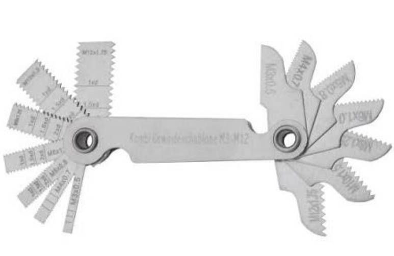
Measure Pitch / TPI: Use an imperial and metric pitch gauge set to find the matching crest-to-crest distance.
Verify with Setting Gauges: Once nominal diameter and pitch are narrowed down, verify the thread form using calibrated thread plug or ring gauges.
What is the difference between an NPT and an NPTF thread gauge?
While both standards share a 60° flank angle and 1:16 taper, NPTF (Dryseal) threads maintain tighter tolerances on crest and root truncation to achieve sealing without compound. Consequently, inspecting NPTF threads requires a coordinated set of L1, L2, and crest/root truncation gauges (such as 6-step crest/root limit gauges) that standard NPT inspections do not use.