Helix angle correction in three-wire measurement compensates for the geometric tilt of measuring wires sitting inside a helical thread groove, preventing an overestimation of the true thread pitch diameter. While standard single-start fine threads rarely produce enough tilt to affect part acceptance, applying lead angle correction becomes mandatory for multi-start threads, Acme and trapezoidal power screws, and coarse-pitch fasteners with small major diameters.
Whether you need to calculate this compensation depends on three factors: the thread lead (L), the pitch diameter (E or d2), and the tolerance class of the workpiece. This guide breaks down the geometric cause of helix angle error, establishes clear thresholds for when correction is required, walks through the exact calculation formula with a worked comparison, and clarifies when to switch from manual wire measurement to functional Thread Gauges on the production floor.

Why the Helix Angle Causes Measurement Error in the Three-Wire Method
The standard simplified three-wire formula assumes that the measuring wires rest inside the thread flanks perpendicular to the screw axis. In reality, an external screw thread advances along a helix, forcing the thread measuring wires to incline at an angle equal to the thread’s helix angle (λ, often referred to as the lead angle in metrology standards).
Because each wire tilts along the helical path, its cross-section in the axial plane becomes slightly elliptical rather than purely circular, and the contact points shift away from the theoretical pitch line. As a result, a micrometer measuring over the wires (M) records a larger dimension than it would on a zero-lead annular groove. Without subtracting the helix angle correction factor (c), the calculated pitch diameter appears artificially oversized, which can cause quality control teams to falsely reject in-tolerance parts or miscalibrate machining offsets.
Key geometric variables governing this error include:
- Lead (L): The axial distance a thread advances in one complete 360° revolution. For single-start threads, L equals the pitch (P). For multi-start threads, L = n × P, where n is the number of starts.
- Pitch diameter (E or d2): The theoretical diameter where the width of the thread ridge and the width of the thread groove are equal.
- Helix angle / lead angle (λ): The angle formed between the tangent to the helix at the pitch cylinder and a plane perpendicular to the thread axis.
- Included thread flank angle (2α): The angle between adjacent thread flanks (e.g., 60° for ISO Metric and Unified UN threads; 29° for Acme threads).
When Is Helix Angle Correction Required? (Critical Thresholds)
Metrology engineers do not need to compute helix angle compensation for every routine thread inspection. Under standard shop conditions, the correction value (c) is negligible when the helix angle remains small relative to the part’s pitch diameter tolerance. However, once the ratio of lead to pitch diameter increases, uncompensated errors quickly consume a significant portion of the allowable tolerance zone.
The decision matrix below outlines standard engineering thresholds for applying helix angle correction across common industrial thread profiles:
| Thread Category | Typical Helix Angle (λ) | Error Impact on Pitch Diameter | Correction Requirement | Recommended Inspection Approach |
|---|---|---|---|---|
| Standard Single-Start Fine Threads (e.g., ISO Metric Fine, UNF) | Less than 2° | Negligible (typically fractions of a micron) | Optional / Usually omitted | Standard three-wire formula or Go/No-Go gauging |
| Standard Single-Start Coarse Threads (e.g., UNC, ISO Coarse) | 2° to 4° | Low to moderate depending on tolerance grade | Recommended for tight tolerance classes | Verify correction factor c against part tolerance |
| Small-Diameter Coarse Threads | 4° to 6° | Moderate to high | Mandatory for precision inspection | Full three-wire formula with helix angle compensation |
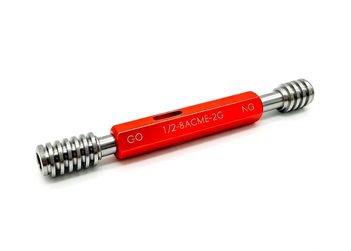
| Acme & Trapezoidal Power Threads | 3° to 8°+ | High (amplified by 29° or 30° flank geometry) | Mandatory | Full correction formula; verify wire contact depth |
| Multi-Start Threads (2-start, 4-start, etc.) | 5° to 15°+ | Severe (often exceeds full pitch diameter tolerance) | Strictly mandatory | Full exact trigonometric formula; never omit c |
Note: exact acceptance thresholds depend on the governing thread standards such as ISO 1502 and ASME B1.2 and the specific tolerance class specified on the engineering drawing.
Step-by-Step Formula for Helix Angle Correction
To determine the compensated pitch diameter (E) during three-wire thread measurement, follow the four-step calculation sequence below.
Step 1: Calculate the Thread Lead and Helix Angle
Determine the axial lead (L) by multiplying the thread pitch (P) by the number of starts (n). Next, compute the helix angle (λ) at the nominal pitch diameter (Enom):
tan λ = L / (π × Enom)
λ = arctan( L / (π × Enom) )
Step 2: Select the Best Wire Size
Choose calibrated thread measuring wires with a mean diameter (w) close to the ideal “best wire size” (wbest), which contacts the thread flanks directly on the pitch cylinder to minimize flank-angle errors:
wbest = P / (2 cos α)
For standard 60° threads (α = 30°), wbest ≈ 0.57735 × P. For 29° Acme and 30° trapezoidal thread gauges (α = 14.5°), wbest ≈ 0.51645 × P.
Step 3: Compute the Helix Angle Correction Factor (c)
For standard 60° threads with moderate helix angles (typically under 5°), engineering handbooks commonly use the simplified approximation formula:
c ≈ (3/2) × w × tan²λ × cos α × cot α
For 60° threads (α = 30°), this simplifies to:
c ≈ 1.299 × w × tan²λ
For high-lead multi-start threads or non-60° profiles (such as 29° Acme or 30° ISO Trapezoidal threads), use the exact trigonometric relationship rather than the simplified approximation, as higher-order terms become significant as λ increases.
Step 4: Calculate the True Pitch Diameter
Subtract the wire constant and the helix angle correction factor (c) from the micrometer measurement over the wires (M):
E = M + P / (2 tan α) − w × (1 + 1 / sin α) − c
For standard 60° threads (α = 30°), the complete compensated equation is:
E = M + 0.86603P − 3w − c
Practical Calculation Example: Single-Start vs. Multi-Start Thread
To see how helix angle correction affects real shop-floor measurements, compare two external 60° threads sharing the same pitch (P = 2.0 mm), nominal pitch diameter (Enom = 18.701 mm), and measuring wire diameter (w = 1.155 mm), differing only in the number of starts.
| Parameter | Case A: Single-Start Thread (n=1) | Case B: 4-Start Thread (n=4) |
|---|---|---|
| Pitch (P) | 2.000 mm | 2.000 mm |
| Axial Lead (L = n × P) | 2.000 mm | 8.000 mm |
| Nominal Pitch Diameter (Enom) | 18.701 mm | 18.701 mm |
| Calculated Helix Angle (λ) | 1.95° (tan λ = 0.03404) | 7.76° (tan λ = 0.13617) |
| Helix Correction Factor (c) | 0.0017 mm (1.7 µm) | 0.0278 mm (27.8 µm) |
| Uncorrected Pitch Diameter Error | +1.7 µm (Negligible for most classes) | +27.8 µm (Exceeds typical precision tolerances) |
In Case A (single-start), omitting the correction factor shifts the reading by less than 2 µm. In Case B (4-start), omitting the correction introduces nearly 28 µm of false oversized error—enough to push an accurate part outside a standard 6g tolerance zone and trigger unnecessary machine adjustments.
Common Measurement Errors & Best Practices in Three-Wire Inspection
Even with accurate helix angle calculations, physical setup variables can distort three-wire pitch diameter readings. Applying consistent metrology controls prevents compounding errors:
- Control measuring force: Excessive anvil pressure on a bench micrometer or supermicrometer elastically compresses the measuring wires into the thread flanks, artificially lowering the reading. Maintain uniform, calibrated measuring force specified for the pitch size.
- Verify flank angle accuracy: The standard wire constant assumes the workpiece thread flank angle (2α) is exact. If the cutting tool or thread rolling die has a flank angle error, using a wire size other than the true “best wire size” (wbest) will introduce additional pitch diameter error.
- Inspect wires for flat spots and wear: Repeated contact under measuring pressure gradually flattens hardened steel or carbide wires. Periodically verify wire roundness and diameter against a master cylinder or three-wire vs. optical comparator verification, and follow a documented gauge wire care and storage protocol between uses.
- Maintain thermal equilibrium: At 20°C (68°F), small temperature differences between steel measuring wires, the micrometer frame, and the workpiece cause measurable expansion. Allow parts and instruments to stabilize before recording final dimensions.
- Cross-check reference standards: Calibrate micrometers and validate inspection setups using traceable master plugs and traceable calibration certificates to ensure measurement consistency across shifts and laboratories.
Three-Wire Method vs. Thread Gauges: Choosing the Right Inspection Method
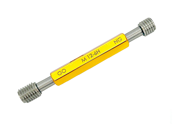
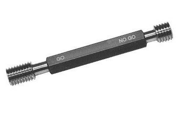
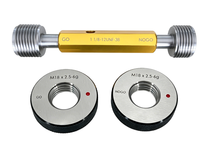
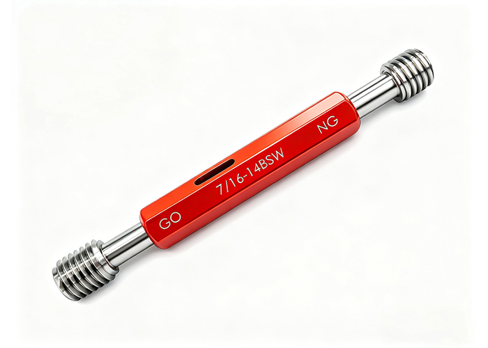
While the three-wire method provides exact variable data for pitch diameter, calculating helix angle corrections and positioning loose wires is slow and requires skilled metrology technicians. In production environments, quality teams balance variable wire measurement with functional Go/No-Go thread ring and plug gauges depending on inspection goals.
| Evaluation Criterion | Three-Wire Measurement | Functional Thread Gauges (Go / No-Go) |
|---|---|---|
| Output Type | Quantitative variable data (exact pitch diameter value) | Qualitative attribute check (Pass / Fail functional acceptance) |
| Elements Checked | Simple pitch diameter only (does not detect lead or form errors) | Cumulative effect of pitch diameter, lead, flank angle, and roundness |
| Inspection Speed | Slow (requires wire setup, micrometer reading, and formula calculation) | Fast (seconds per part; suited for 100% or high-frequency sampling) |
| Operator Skill Level | High (requires metrology training and calculation accuracy) | Moderate (straightforward tactile go/no-go verification) |
| Primary Applications | First-article inspection (FAI), tool setup, calibration labs, multi-start verification | High-volume production lines, receiving inspection, final shipment QC |
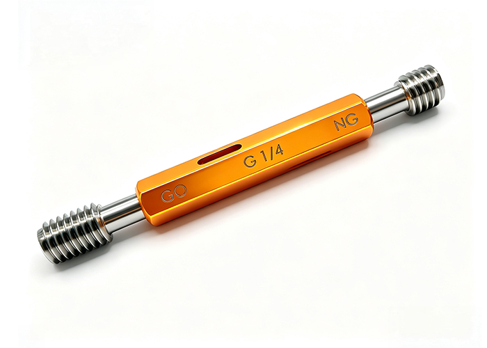
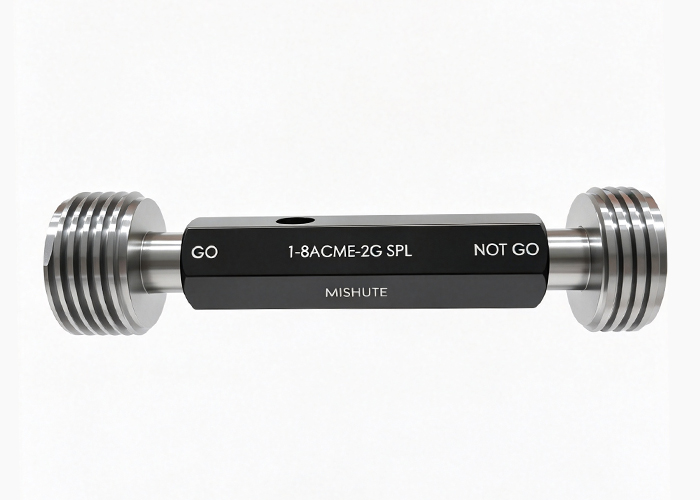
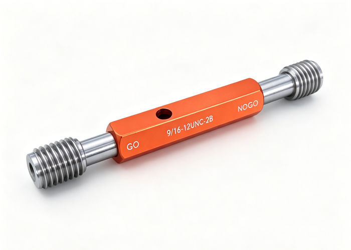
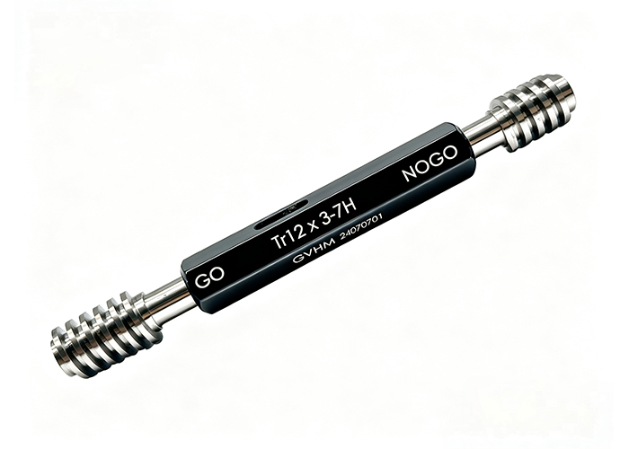
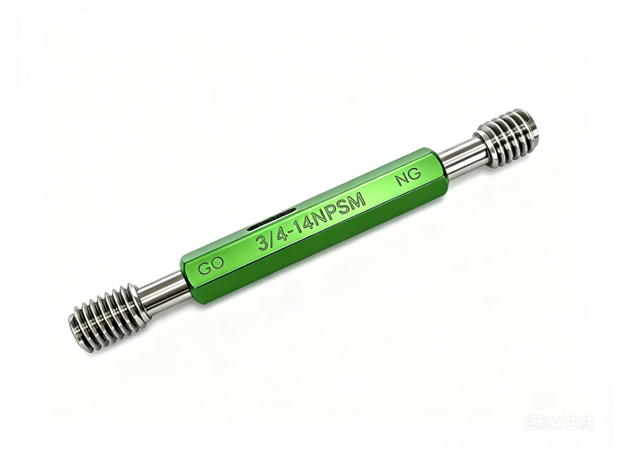
For optimal quality control, use three-wire measurement with helix angle correction during initial CNC setup, first-article verification, and gauge calibration, while deploying dedicated Go/No-Go Thread Gauges on the shop floor—following a documented Go/No-Go gauging operating procedure—to verify functional assembly fit rapidly.
Key Takeaways
- Root cause: Thread measuring wires tilt along the thread’s helix angle (λ), causing uncompensated three-wire measurements to overestimate the true pitch diameter.
- When to apply: Helix angle correction is typically negligible for single-start fine threads (λ under 2°) but is strictly mandatory for multi-start threads, Acme/trapezoidal power screws, and coarse small-diameter threads.
- Calculation logic: Always calculate axial lead (L = n × P) before computing tan λ = L / (π E), then subtract the correction factor (c) from the compensated pitch diameter equation.
- Shop-floor workflow: Combine three-wire measurement for first-article variable data with functional Go/No-Go Thread Gauges for fast, repeatable production line inspection.
Frequently Asked Questions (FAQ)
Does helix angle correction apply to both internal and external threads?
Helix angle correction in the three-wire method applies strictly to external threads, as standard measuring wires cannot be suspended inside an internal bore. Internal threads are typically inspected using thread plug gauges, internal thread micrometers, or coordinate measuring machines (CMMs). For a structured overview, see our guide to internal vs. external thread inspection.
What is the difference between lead angle and helix angle in thread measurement?
In screw thread metrology, the lead angle (λ) is measured between the thread helix and a plane perpendicular to the thread axis, whereas the helix angle (ψ) is measured from the thread axis itself (λ + ψ = 90°). Standard three-wire correction formulas use the lead angle (tan λ = L / π E), though many shop-floor guides refer to this value as the helix angle.
Can a thread pitch micrometer eliminate the need for helix angle correction?
Thread pitch micrometers use conical spindle and V-anvil tips that contact the thread flanks directly, avoiding loose wires, but they still experience minor contact-point shifts on steep multi-start helices. For high-lead multi-start threads, compensated three-wire measurement or custom thread gauge specifications for OEM orders remain more reliable.
Explore Thread Gauges or share your multi-start and trapezoidal thread drawings with the MIHE engineering team to confirm the right gauging configuration for your inspection workflow.