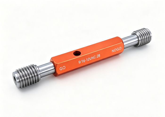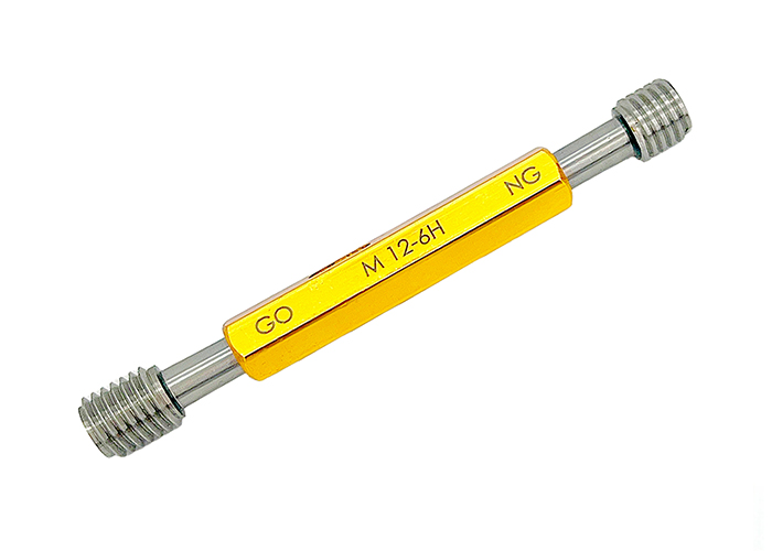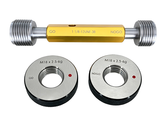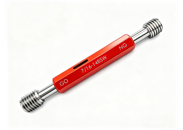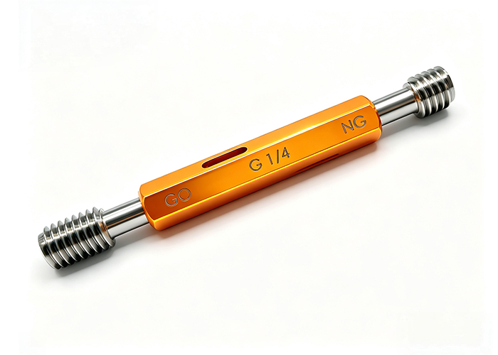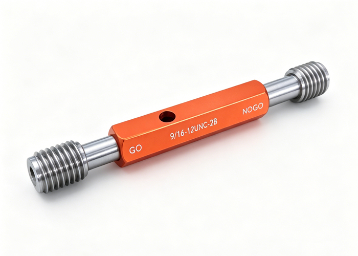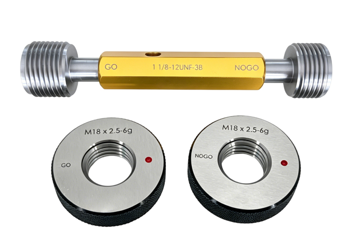
Thread gauge calibration determines whether precision manufacturing tolerances are maintained or compromised by worn tooling. The core difference between the three-wire method and an optical comparator comes down to contact mechanics versus non-contact projection: the three-wire method directly measures the pitch diameter of external threads (such as thread plug gauges) with high mechanical repeatability, whereas an optical comparator evaluates two-dimensional profile geometry (flank angles, lead, and root radii) using magnified silhouettes. Neither method, however, directly calibrates closed-profile internal threads found in thread ring gauges.
Choosing the right inspection workflow depends on gauge geometry, required measurement uncertainty, and whether you are verifying pitch diameter or diagnosing tooling form errors. This guide breaks down the physical mechanics of both techniques, identifies their measurement limitations, explains how thread ring gauges are calibrated in certified labs, and outlines best practices for maintaining production-floor metrology standards.
The Core Challenge in Thread Gauge Calibration: Pitch Diameter Precision
The operational fit of any threaded assembly depends primarily on pitch diameter—the theoretical cylinder where thread tooth thickness equals the width of the thread space. Unlike major or minor diameters, which can be checked with standard micrometer anvils, pitch diameter lies on an angled 3D flank that cannot be measured directly without specialized intermediate contacts or optical tracing.
Calibrating precision thread gauges requires controlling three interactive variables:
Flank Angle Error: Deviations along the 60° (metric/unified) or 55° (Whitworth) tooth profile distort where the gauge seats.
Lead / Pitch Error: Progressive deviation along the screw axis causes pitch diameter virtual expansion, altering go/no-go functionality.
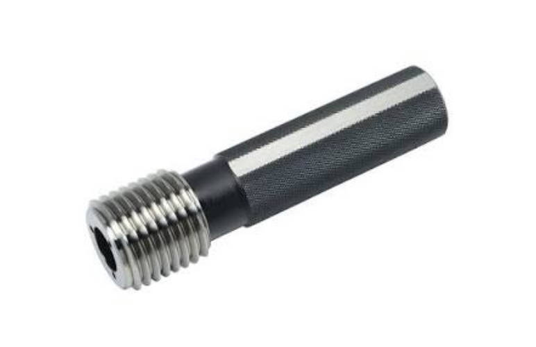
Geometric Accessibility: Thread plug gauges present exposed external threads easily accessible to micrometers, whereas thread ring gauges enclose internal threads within a solid steel ring, blocking standard external probing systems.
Achieving micro-inch measurement repeatability requires matching the metrology tool to the physical geometry of the gauge.
The Three-Wire Method: Principles, Mechanics, and Calibration Scope
The three-wire method is the recognized industry standard for direct, traceable measurement of pitch diameter on external threads, including thread plug gauges and master setting plugs.
How the Three-Wire System Works on Thread Plug Gauges
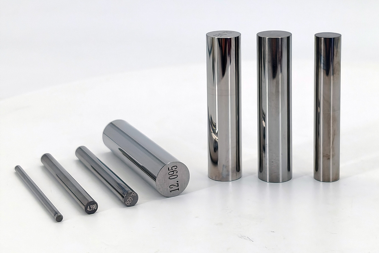
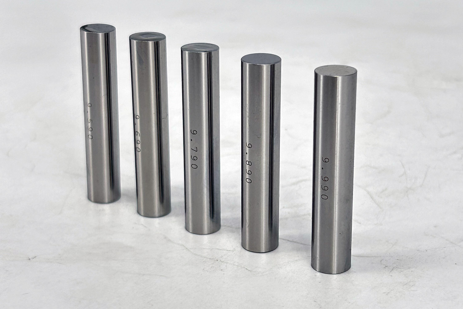
The method positions three precision-ground, calibrated steel cylinders (wires) into the thread grooves: two wires sit on one side, and one sits opposite. An outside micrometer or a horizontal length measuring machine with flat, parallel anvils then measures the dimension over the wires ($M$).
| Layer / Zone | Mechanical Component | Function in Measurement Setup |
| Top Measurement Boundary | Upper Micrometer Anvil | Provides a flat, parallel reference plane applying controlled measuring force |
| Upper Contact Points | Wire 1 & Wire 2 (Calibrated Wires) | Seat symmetrically into two adjacent thread grooves along the top flank |
| Gauge Centerline | External Thread Plug Profile | Thread tooth flanks cradle the wires at the theoretical pitch diameter line |
| Lower Contact Point | Wire 3 (Calibrated Wire) | Seats into the directly opposing lower thread groove along the bottom flank |
| Bottom Measurement Boundary | Lower Micrometer Anvil | Forms the opposing parallel reference plane for the over-wire reading ($M$) |
To eliminate flank contact errors, metrology standards dictate the use of best-size wires—cylinders with a specific diameter ($G$) that contact the thread flanks precisely at the pitch line:
$$G = \frac{P}{2} \sec(\alpha)$$
(where $P$ is the thread pitch and $\alpha$ is the half-angle of the thread profile).
Once the measurement over wires ($M$) is recorded, the pitch diameter ($E$) is calculated using standard formulations that factor in wire size, thread angle, and helix angle corrections.
Critical Metrology Factor: Anvil measuring force must be carefully controlled (typically 2.5 to 40 ounces, depending on thread pitch and applicable standards like ASME B1.2) to prevent elastic deformation between the wire and the thread flank, which skews pitch diameter readings downward.
The Critical Limitation: Why Three-Wire Cannot Directly Calibrate Thread Ring Gauges
Because the three-wire method relies on opposing external anvil contacts compressing wires inward against external flank grooves, it cannot be applied to internal threads. The closed bore of a thread ring gauge prevents standard wire placement and external micrometer measurement, making direct three-wire calibration impossible for ring gauges.
The Optical Comparator: Optical Projection and Profile Inspection
An optical comparator (shadowgraph) uses telecentric illumination to project an enlarged 2D shadow of a part onto a translucent viewing screen equipped with crosshairs and digital readout scales.
Non-Contact Profile Analysis and Angle Verification
Optical comparators excel at non-destructive, non-contact evaluation of thread form geometry. Technicians use magnified overlays or digital edge detection to inspect:
Flank angles and half-angle symmetry (detecting tool tilt or wear)
Crest and root radii (spotting burrs, tool chipping, or improper root truncation)
Gross lead pitch variations across several consecutive threads
Because it does not physically touch the part, an optical comparator avoids anvil force deformation and surface scratching on softer or coated master gauges.
The Helix Angle Challenge: Understanding Shadow Distortion
Despite its versatility for form inspection, an optical comparator has distinct limitations when measuring pitch diameter:
Shadow Overlap from Helix Angle: Threads are helical spirals, not perpendicular 2D grooves. As light travels parallel to the gauge centerline, the tilted thread flank on the near and far sides casts overlapping shadows, masking the true flank edge at the theoretical pitch line.
Imperfect Tilt Compensation: While advanced comparators allow the light source and stage to swivel to match the thread lead angle, variations across thread depth mean the projection edge still displays slight focal curvature rather than a knife-sharp boundary.
Internal Ring Gauge Occlusion: An optical comparator cannot project an unobstructed shadow through the internal bore of a small, solid thread ring gauge.
Head-to-Head Comparison: Three-Wire Method vs. Optical Comparator
| Evaluation Factor | Three-Wire Method | Optical Comparator |
| Measurement Type | Physical mechanical contact | Non-contact optical silhouette |
| Target Gauges | Thread plug gauges, master setting plugs | Thread plug gauges, external thread templates |
| Primary Measured Parameter | Exact pitch diameter | Flank angle, root/crest radii, thread form |
| Measurement Uncertainty | Very low (sub-micron repeatability) | Moderate (limited by edge focus and optical diffraction) |
| Internal Ring Gauge Capability | Not capable (geometry limitation) | Not capable for solid rings (light path obstructed) |
| Influence of Helix Angle | Solved mathematically via lead correction formulas | Distorts optical shadow edges if stage is unaligned |
| Speed & Setup | Slower; requires wire handling and arithmetic calculation | Fast; immediate visual verification of thread form |
While the three-wire method remains the legal and metrological benchmark for verifying external pitch diameter, the optical comparator serves as a complementary tool for validating tooth form integrity and identifying structural wear on industrial thread gauges.
How Thread Ring Gauges Are Actually Calibrated: The Industry Solution
Because neither the three-wire method nor standard optical projection directly measures closed internal thread ring gauges, calibration laboratories rely on two standardized alternatives.
| Calibration Method | Primary Environment | Operating Mechanism | Key Advantage |
| Calibrated Setting Plugs | Shop Floor / In-House QC | Truncated Class W master plug gauge (pre-calibrated via 3-wire method) evaluates functional fit and friction drag | Low equipment cost; fast go/no-go functional assessment |
| Direct Internal Metrology | Accredited Metrology Lab | Universal Length Measuring (ULM) machine using opposing calibrated ball styli directly contacting internal thread flanks | Absolute coordinate tracking; zero operator subjectivity |
1. Calibrated Setting Plug Gauges (Master Plugs)
In regular factory quality control and gauge re-certification, thread ring gauges are calibrated using Class W truncated setting plug gauges:
The setting plug’s external pitch diameter is first calibrated using the three-wire method.
The technician cleans and lubricates the ring gauge.
The ring gauge is turned onto the truncated master plug to evaluate pitch diameter fit, thread flank engagement, and drag consistency.
If a ring gauge binds or turns past its limit, its adjustment mechanism (for adjustable split rings) is reset and sealed, or solid rings are condemned for wear.
2. Direct Internal Metrology (Universal Length Measuring Machines)
In accredited metrology laboratories, direct calibration of solid thread ring gauges is performed on a Universal Length Machine (ULM) or high-accuracy coordinate measuring machine (CMM) configured with internal thread probing accessories:
Two independent, calibrated ball styli enter the ring bore from opposite directions.
The styli contact opposing thread flanks at the exact pitch line coordinates.
Electronic encoders record pitch diameter, drunkenness, and taper without relying on subjective operator touch.
Best Practices for Selecting and Maintaining Calibrated Thread Gauges
A gauge calibration system is only as reliable as the gauge material and the recall cycle governing the inspection inventory.
| Stage | Action Item | Verification Objective |
| 1. Receiving Inspection | Verify manufacturer certificate against standard tolerances (ANSI/ASME B1.2 or ISO 1502) | Ensure out-of-box compliance before tooling touches production parts |
| 2. Production Deployment | Enforce pre-cleaning of threaded parts and zero-force gauge entry | Prevent abrasive metal chip wear and premature flank damage |
| 3. Routine In-House Check | Inspect ring gauges against truncated setting plugs on a recurring cycle | Catch pitch diameter wear before out-of-tolerance parts reach assembly |
| 4. Accredited Recalibration | Send gauges to ISO/IEC 17025 accredited labs for full mechanical or ULM recertification | Maintain unbroken NIST/international traceability records |
Sourcing Considerations
When procuring certified thread plug and ring gauges, ensure that manufacturing tolerances comply with applicable standards (such as ASME B1.2 or ISO 1502). Gauges ground from high-stability tool steel (such as oil-hardened tool steel or high-grade bearing steel) resist abrasive shop-floor wear, preserving pitch diameter stability and extending recalibration intervals.
Key Takeaways
Targeted Roles: The three-wire method is the gold standard for measuring pitch diameter on external threads (plug gauges), while the optical comparator is designed for non-contact profile and angle inspection.
Geometry Restrictions: Neither the three-wire method nor standard optical projection can measure the closed internal pitch diameter of thread ring gauges directly.
Ring Gauge Calibration: Thread ring gauges are calibrated either functionally using three-wire-verified setting plug gauges or directly using horizontal length measuring machines (ULM) equipped with internal ball-tip probes.
Error Prevention: Three-wire measurements require strict control of measuring force and best-size wire geometry, whereas optical readings must account for helical shadow distortion along the pitch line.
FAQ
Can pitch diameter be measured with a standard caliper or micrometer without wires?
No. Standard micrometer or caliper jaws make contact across the thread crests (major diameter) rather than entering the flank angle. Measuring pitch diameter requires calibrated thread wires, point-and-v-anvil thread micrometers, or specialized metrology probes.
Why do optical comparators struggle to measure pitch diameter on small thread plugs?
Small-pitch threads have steep helix profiles and tightly packed tooth geometry. When illuminated, adjacent thread flanks cast overlapping shadows that obscure the theoretical pitch line, reducing edge-detection clarity and increasing measurement uncertainty.
How often should thread plug and ring gauges be calibrated?
Calibration intervals depend on production volume, part material abrasiveness, and tolerance severity. Standard practice ranges from 6 to 12 months for active gauges, though high-wear shop-floor gauges should be inspected monthly against master setting plugs.
What is the difference between a truncated setting plug and a basic plug gauge?
A truncated setting plug has threads with both a full-form section and a truncated section where thread crests have been ground flat. This allows inspectors to verify pitch diameter fit independently of minor root or crest interference when setting thread ring gauges.