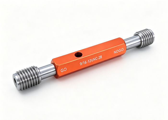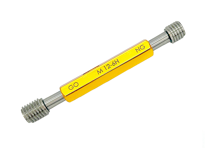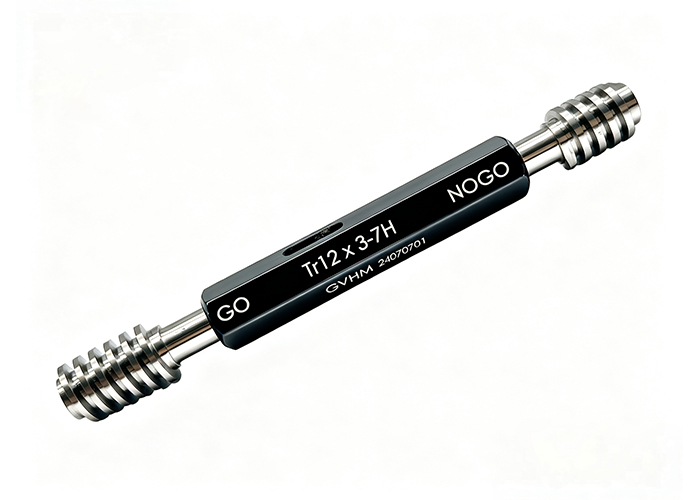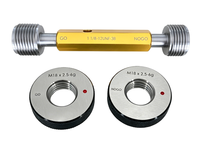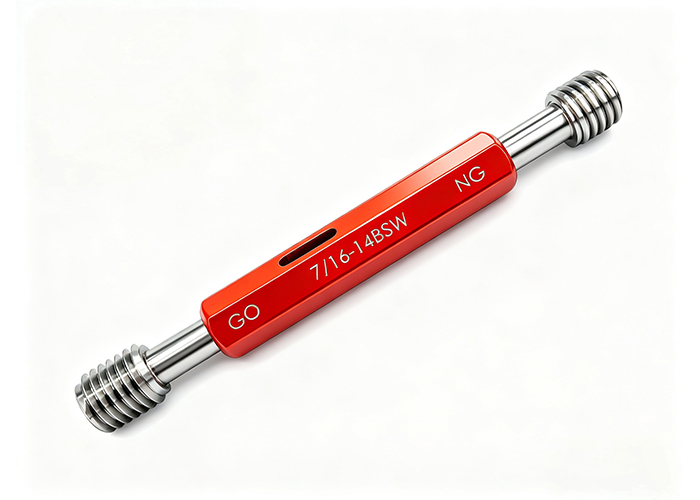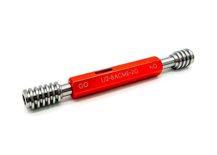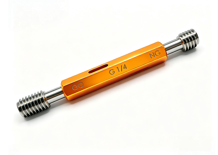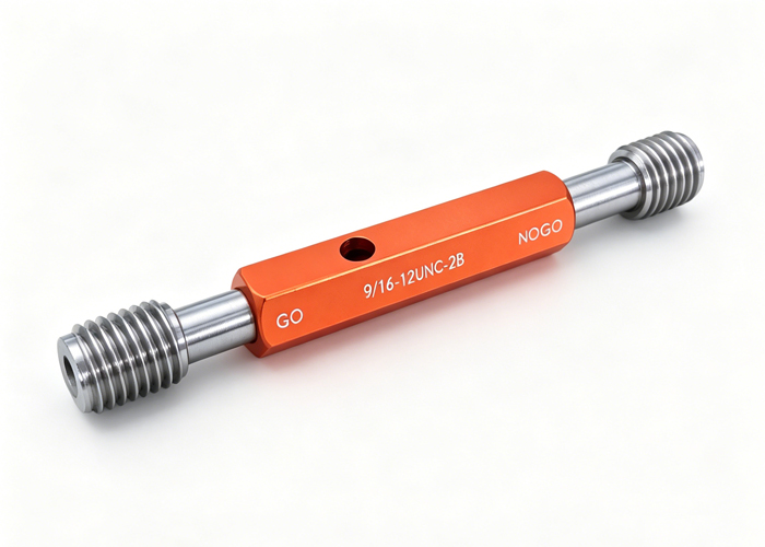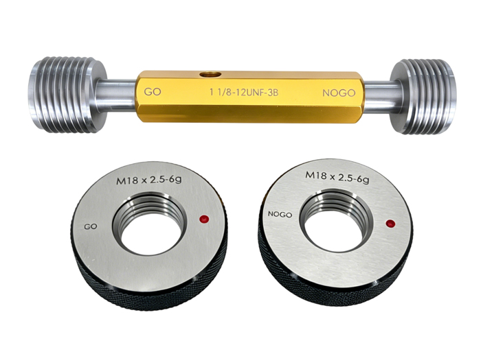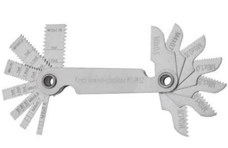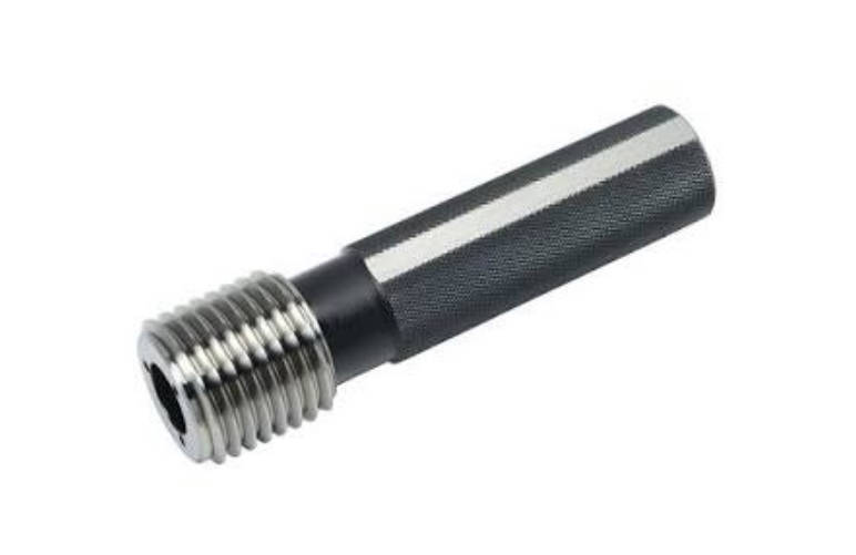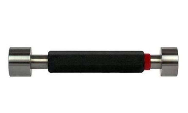
Thread inspection determines whether a threaded fastener, machined bore, or tapped component will assemble correctly under working loads. The choice between thread plug gauges and thread ring gauges comes down to a fundamental mechanical distinction: thread plug gauges inspect internal threads (such as tapped holes and nuts), while thread ring gauges inspect external threads (such as bolts, studs, and threaded shafts).
Both tools rely on fixed-limit Go/No-Go principles to evaluate pitch diameter, flank angles, and lead variation without requiring complex optical or coordinate measuring setups on the shop floor. Selecting the right gauging method requires understanding how internal and external thread geometries interact, how standard tolerance classes apply, and how to operate these inspection tools without accelerating gauge wear or passing non-conforming parts.
1. Core Differences: Internal vs. External Thread Inspection at a Glance
Machined threads consist of mating geometric features that must operate within standardized boundary limits. A thread plug gauge acts as a calibrated “mating bolt” to check an internal cavity, whereas a thread ring gauge acts as a calibrated “mating nut” to verify an external shaft.
Using high-precision standard and custom thread gauges provides a rapid, pass/fail verification method directly at the CNC workstation or quality assurance station.
| Feature / Criterion | Thread Plug Gauges | Thread Ring Gauges |
| Inspection Target | Internal threads | External threads |
| Common Workpieces | Tapped holes, engine blocks, manifolds, nuts | Machined bolts, threaded studs, precision shafts |
| Gauge Construction | Threaded cylindrical plug mounted on a handle | Cylindrical disc with a precision-ground threaded bore |
| Key Parameters Checked | Minor diameter, pitch diameter, lead, flank angle | Major diameter clearance, pitch diameter, lead angle |
| Go Member Function | Verifies minimum pitch diameter & maximum material | Verifies maximum pitch diameter & maximum material |
| No-Go Member Function | Verifies maximum pitch diameter (prevents loose fits) | Verifies minimum pitch diameter (prevents loose fits) |
2. Thread Plug Gauges: Principles and Procedures for Internal Threads
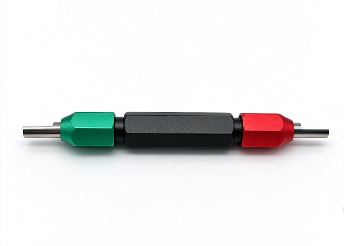
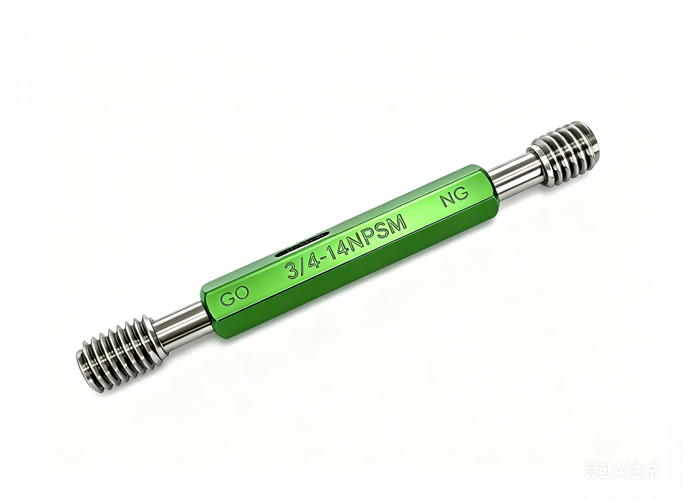
A thread plug gauge checks the internal pitch diameter and thread form of tapped or internally milled holes. In typical industrial workflows, these tools are supplied as double-ended assemblies with a central hexagonal or taper-lock handle holding both a “Go” member (longer thread body) and a “No-Go” member (shorter thread body).
| Gauge Section | Visual Indicator / Length | Primary Function | Pass/Fail Condition |
| Go Member | Green band / Noticeably longer threaded profile | Verifies Maximum Material Condition (MMC) | Must thread fully through the hole without binding |
| Handle / Body | Hexagonal or knurled aluminum/steel grip | Provides ergonomic grip and engraved specification data | N/A (Tool interface and identification mark) |
| No-Go Member | Red band / Noticeably shorter threaded profile | Verifies Least Material Condition (LMC) | Must not rotate more than 2 to 3 complete turns |
Design Variations for Shop-Floor Integration
Taper-Lock Plug Gauges: Typically used for smaller diameter threads (commonly below 1.5 inches or M38). The threaded gauge ends taper press-fit into the handle, allowing quick replacement when a gauge wears out.
Reversible Plug Gauges (Trilock / Wire Type): Designed with identical ends on a single member. When the leading threads on the Go side wear down from abrasive chips, the member can be reversed in the collet or handle, effectively doubling tool life before replacement.
Large-Diameter Segmented Gauges: For large bores, solid steel plugs become heavy and unwieldy for manual inspection. Annular or progressive segmental designs reduce tool weight to maintain operator tactile sensitivity.
How Internal Thread Features Are Verified
Maximum Material Condition (MMC): The Go plug verifies that the internal thread is not cut too small. If the hole is undersized, the mating fastener will bind or seize during final assembly.
Least Material Condition (LMC): The No-Go plug verifies that the machinist has not removed excessive metal. An oversized internal thread strips out under mechanical tension because thread shear area drops below design limits.
3. Thread Ring Gauges: Ensuring Accuracy for External Threads and Fasteners
Where plug gauges check internal boundaries, precision thread ring gauges verify male thread profiles on fasteners, hydraulic fittings, and turned shafts.
External threads present different manufacturing challenges than internal bores, such as tool deflection on lathes, chattered crests, and cumulative lead errors. Ring gauges consolidate these geometric variables into an immediate functional verification.
Solid vs. Adjustable Ring Gauges
Industrial manufacturers typically choose between two mechanical designs:
Solid Thread Ring Gauges: Ground from a single piece of stabilized tool steel. They offer high structural rigidity and eliminate tampering risks on the production floor because the dimensional envelope cannot shift. However, once wear exceeds permissible tolerances, solid rings must be retired or reworked.
Adjustable Thread Ring Gauges: Feature a slotted circumference controlled by an adjusting screw and locking mechanism. These gauges are calibrated and sealed against a master setting plug. While they allow recalibration after minor abrasive wear, they require strict tool-crib discipline to prevent unauthorized adjustment by machine operators.
When selecting between solid and adjustable variants, high-volume production lines running standard fastener batches generally favor solid rings for tamper resistance, whereas specialized toolrooms often deploy adjustable rings alongside dedicated master setting plugs.
4. The Go / No-Go Verification Rule: Proper Inspection Criteria & Common Pitfalls
Functional gauging relies on a simple principle: The Go gauge must assemble completely, and the No-Go gauge must not assemble. Misinterpreting what defines “assembly,” however, leads to scrapped parts or false acceptance.
| Gauge Member | Inspection Target | Verification Objective | Standard Pass Criteria | Non-Conformance Indication |
| Go Gauge | Entire thread length | Maximum Material Condition (ensures assembly fit) | Threads freely and smoothly by hand across full depth | Binds, jams, or stops prematurely (Undersized internal / Oversized external) |
| No-Go Gauge | Pitch diameter boundary | Least Material Condition (prevents loose fits) | Enters no more than 2 to 3 complete rotations | Screws all the way into or over the component (Oversized internal / Undersized external) |
The Standard Inspection Procedure
Clean and Deburr the Part: Machining chips, coolant sludge, or exit-thread burrs can wedge between the gauge and part, causing premature binding or galling the ground gauge surfaces.
Apply the Go Gauge Manually: Thread the Go member onto or into the workpiece by hand without forcing. It should rotate freely through the entire specified thread engagement length.
Apply the No-Go Gauge Manually: Present the No-Go member squarely to the thread entry.
Standard Acceptance Rule: Under international ISO and ASME guidelines, the No-Go gauge may engage the entry chamfer but must not rotate more than two to three full turns (depending on the specific standard and thread pitch).
If the No-Go gauge winds entirely into or onto the workpiece, the pitch diameter is out of tolerance, rendering the part non-compliant.
Practical Pitfalls to Avoid on the Line
Forcing the Gauge: Gauges are dimensional comparators, not thread chasers or taps. Applying wrenches, pliers, or excessive hand torque deforms gauge flanks and creates false clearance.
Temperature Discrepancies: Inspecting hot parts straight out of a CNC milling or turning center leads to measurement errors. Steel parts contract as they cool down to ambient temperature ($20^\circ\text{C} / 68^\circ\text{F}$ standard baseline), turning a borderline “pass” into an undersized rejection.
Disregarding Lead Error: If a thread has pitch or lead stretch caused by incorrect machine feed rates, a Go gauge may bind even when the actual pitch diameter appears correct on a thread micrometer. The Go gauge serves as a compound check for form, lead, and diameter simultaneously.
5. Engineering Selection Framework: How to Specify the Right Gauges for Your Project
Specifying the correct inspection tools requires alignment with the design print’s tolerance classes and industry standards. Ordering an incompatible gauge standard leads to costly inspection disputes between suppliers and end-customers.
To ensure proper engagement and compliance, verify your procurement requirements against the checklist below:
Thread Standard: Specify Metric ISO (e.g., ISO 965), Unified National (e.g., UNC, UNF per ASME B1.1), or Pipe Thread (e.g., NPT per ASME B1.20.1, BSPT per ISO 7).
Fit and Tolerance Class:
Internal Threads (Plug Gauges): Specify classes such as 6H, 6G, or Unified classes 2B, 3B.
External Threads (Ring Gauges): Specify classes such as 6g, 6e, or Unified classes 2A, 3A.
Hole or Thread Geometry: Identify whether internal threads are blind or through-holes. Blind holes with limited relief require truncated or bottoming gauge designs.
Workpiece Material Abrasiveness: When gauging cast iron, high-silicon aluminum, or abrasive composites, specify hard-chrome plating or specialized tool steels to minimize abrasive flank wear.
Calibration Traceability: Ensure gauges are ordered with certified calibration certificates verifying pitch diameter, major/minor diameters, and tooth form against NIST or equivalent international standards.
For engineering teams evaluating production lines, exploring MIHE thread gauge manufacturing capabilities provides access to application-specific tolerance classes, custom pitch profiles, and hardened steel designs engineered for high-cycle production environments.
6. Frequently Asked Questions (FAQ)
Can a thread plug gauge be used to check an external thread?
No. A thread plug gauge features external male threads engineered exclusively to inspect internal female threads (such as tapped bores and nuts). External threads on shafts and bolts require a female thread ring gauge or a dedicated thread snap caliper.
How often should thread plug and ring gauges be calibrated?
Calibration frequency depends on usage cycles, workpiece material abrasiveness, and internal quality management standards (such as ISO 9001). Under standard machining conditions, working gauges should be inspected on a fixed interval—such as every 6 to 12 months—or after a specified cycle count (e.g., 2,500 to 5,000 insertions). Gauges exposed to abrasive materials like cast iron require shorter inspection cycles.
What is the difference between setting plugs and working ring gauges?
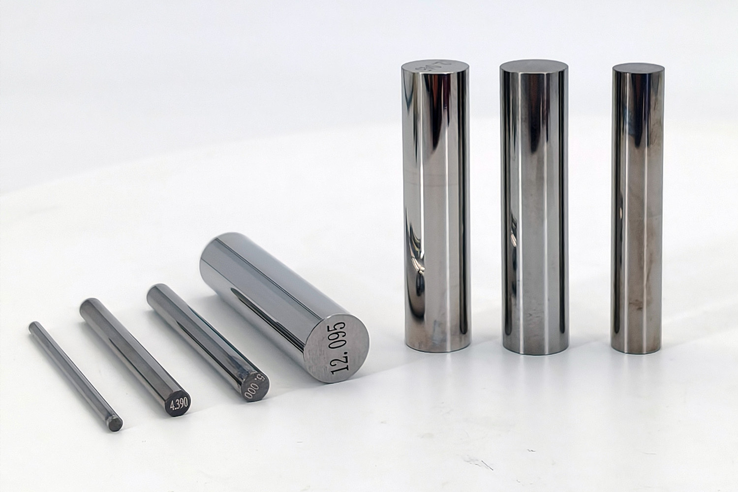
A working ring gauge is used daily on the production floor to check machined parts. A setting plug gauge (master plug) is not used for part inspection; its sole purpose is to establish, adjust, and calibrate adjustable thread ring gauges in a controlled inspection laboratory.
Why does a Go gauge enter a part, but a bolt of the same nominal size will not thread in?
This issue typically stems from plating thickness or thread lead error. If a part passes a standard gauge before surface coating, plating buildup (such as zinc, nickel, or anodizing) will reduce clearances, causing bolts to bind. Ensure pre-plate or post-plate gauge tolerances are specified in the engineering drawing.
7. Optimize Your Quality Control with Precision Gauging Solutions
Consistent thread inspection prevents assembly failures, structural bolt stripping, and fluid leakage in critical assemblies. Implementing the right combination of Go/No-Go thread plug gauges for your tapped features and precision thread ring gauges for your external shafts establishes repeatable quality control right at the machine.
When project drawings call for non-standard thread pitches, specialized tolerance classes, or wear-resistant toolroom gauges, working with an experienced manufacturer ensures that your inspection tools reflect exact drawing requirements.
Key Takeaways
Inspection Roles: Thread plug gauges inspect internal female threads (tapped holes); thread ring gauges inspect external male threads (bolts and shafts).
Go vs. No-Go Function: Go members verify that the component does not exceed Maximum Material Condition (ensuring assembly); No-Go members confirm the component does not exceed Least Material Condition (preventing excessive looseness).
Acceptance Criteria: A Go gauge must assemble completely across the engagement length by hand; a No-Go gauge must disengage after no more than two to three rotations.
Specification Matching: Always match gauge tolerance classes directly to drawing specifications (e.g., 6H/6g for ISO Metric, 2B/2A for Unified).
Maintenance & Handling: Clean, deburr, and cool down workpieces before gauging to avoid premature gauge flank wear and false rejections.
FAQ
Q: Can a thread plug gauge inspect external threads?
A: No. Thread plug gauges only verify internal threads. External threads require thread ring gauges or thread snap gauges.
Q: What is the maximum allowable entry for a No-Go gauge?
A: Under standard ASME and ISO rules, the No-Go gauge should not enter more than two to three complete turns into or onto the part.
Q: What is the purpose of a master setting plug?
A: Master setting plugs are calibration standards used to adjust and calibrate adjustable thread ring gauges, not for inspecting production parts.
Q: When should pre-plate gauges be selected?
A: Pre-plate gauges must be used when workpieces undergo electroplating, anodizing, or heavy coating that will deposit material and reduce thread clearances post-machining.