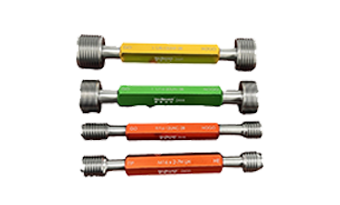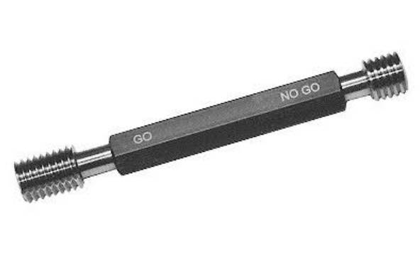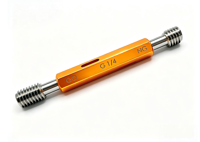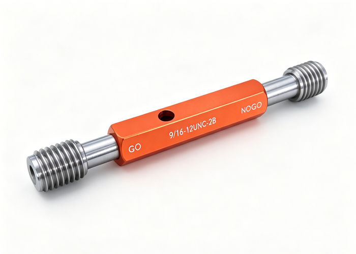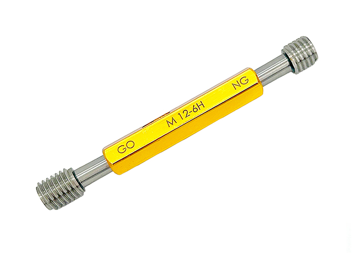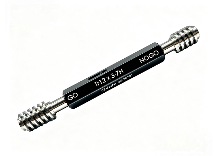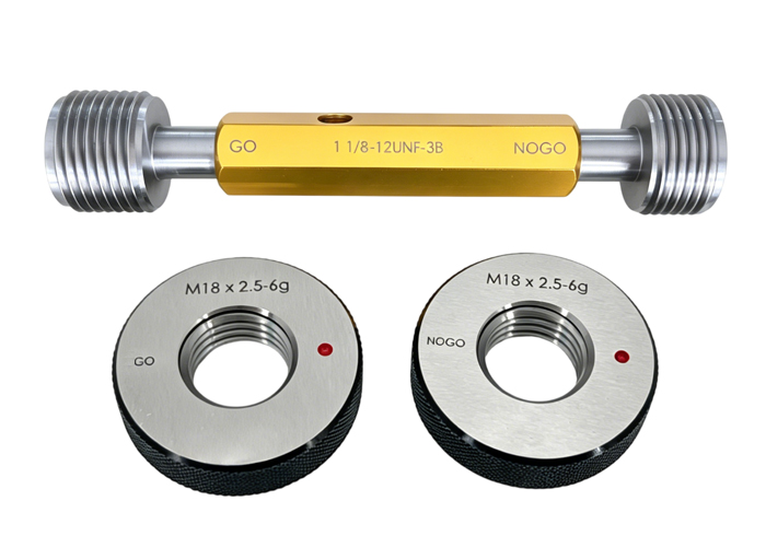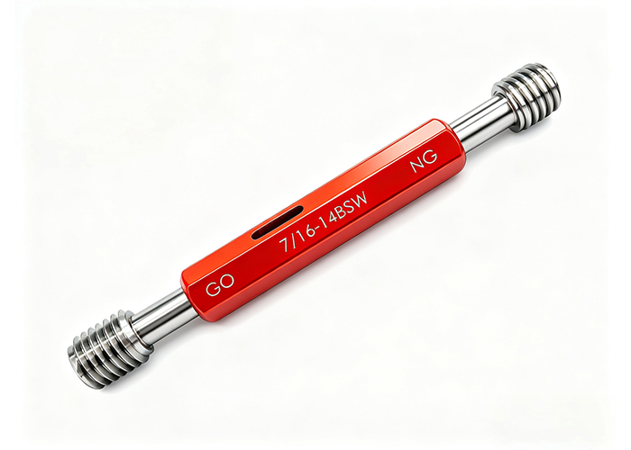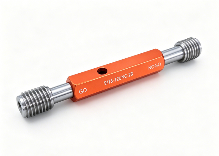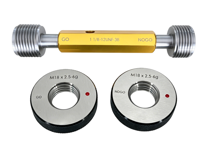
Interpreting a thread gauge calibration certificate correctly determines whether your production line runs within specification or produces thousands of non-conforming threaded parts. At its core, verifying a calibration certificate requires comparing the actual measured pitch diameter against design tolerance limits while confirming that measurement uncertainty remains within acceptable calibration ratios.
Understanding how to read thread gauge calibration certificate data helps quality assurance engineers, machinists, and procurement teams distinguish between a functional gauge, a worn tool requiring retirement, and an invalid calibration document. This guide breaks down the essential sections of a metrology report, details critical dimensional parameters, clarifies acceptance criteria for Go and No-Go members, and establishes a clear protocol for handling out-of-tolerance results.
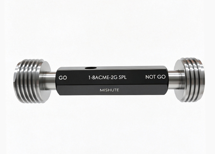
Decoding Your Thread Gauge Calibration Report: Why Verification Matters
Receiving a gauge with an accompanying document does not automatically guarantee compliance. A thread gauge inspection report serves as legal and technical proof that a specific physical standard matches international engineering criteria.
Relying on a gauge without verifying its certificate introduces three distinct failure modes into manufacturing:
Undetected Process Drift: A worn Go gauge that has expanded beyond its allowable limit (or worn undersize on a plug) accepts parts that will seize or fail during end-user assembly.
False Rejection Costs: An out-of-tolerance No-Go gauge rejects acceptable production lots, creating unnecessary scrap and rework.
Audit Non-Conformance: Quality management standards such as ISO 9001, IATF 16949, and AS9100 require verified measurement traceability. Presenting a certificate missing environmental parameters or formal accreditation can lead to immediate audit findings.
A structured document review prevents these outcomes before the tool ever touches a production part.
The Core Anatomy of a Thread Gauge Calibration Certificate
Standard inspection documents issued by accredited laboratories follow a consistent layout divided into administrative metadata, environmental conditions, dimensional inspection values, and compliance statements.
| Report Section | Key Parameters & Verification Points | Metrological Purpose |
| 1. Calibration Certificate Metadata | • Serial / Tool ID • Calibration Date & Recall/Due Date • Applicable Thread Standards (ASME B1.2, ISO 1502) • Lab Accreditation (ISO/IEC 17025) | Establishes legal chain-of-custody, serial traceability, and authority of the testing laboratory. |
| 2. Environmental & Traceability Baseline | • Standard Reference Temperature: 20°C (68°F) • Thermal Equilibrium Confirmation • Traceable Master Gauge Serial Numbers • NIST / National Metrology Institute Traceability | Guarantees thermal expansion errors do not skew micro-inch or micron-level measurements. |
| 3. Quantitative Measurement Results | • Pitch Diameter (PD) Actual vs. Nominal • Major and Minor Diameters • Cumulative Lead (Pitch) Accuracy • Half-Flank Angle Conformity | Provides the physical inspection data necessary to evaluate geometry against drawing specifications. |
| 4. Compliance & Uncertainty Statement | • Expanded Measurement Uncertainty ($U, k=2$) • Test Uncertainty Ratio (TUR $\ge$ 4:1) • Guard Banding / Decision Rule • Final Disposition (Pass / Fail / Limited) | Formally certifies whether the measured deviations statistically satisfy tolerance thresholds. |
Administrative & Traceability Metadata (Header Details)
The top section of the report establishes chain-of-custody and tool identification. A valid document must display:
Gauge Identification: The serial number etched onto the gauge body must match the certificate exactly. Generic certificates referencing only part numbers without serial tracking are non-traceable certificates of conformance, not true calibration certificates.
Calibration Date and Interval: Indicates the date of testing and recommended recalibration timeframe based on quality manual requirements.
Governing Standard: Specific thread specifications applied during evaluation (such as ASME B1.2, ASME B1.16M, ISO 1502, or DIN 13).
Accreditation Marks: Verification that the testing facility operates under ISO/IEC 17025 accreditation, accompanied by traceability documentation linking measuring masters back to national metrology institutes.
Environmental & Standard References (Test Conditions)
Dimensional metrology relies on stable thermal conditions. Steel expands and contracts based on ambient temperature; therefore, international standards mandate a reference temperature of 20°C (68°F).
The report must record ambient temperature and relative humidity during inspection. If measurements occur outside 20°C without documented thermal compensation, precision measurements in the sub-micron range lose technical validity.
When sourcing new inspection tools, procuring factory-certified thread gauges with documented serial identification and baseline environmental data ensures initial production setup aligns with international audit baselines.
How to Interpret Dimensional Inspection Data: The Critical Values
The center of the report contains the quantitative data. Reading these tables requires understanding the mathematical relationship between the stated columns.
| Inspection Parameter | Stated Nominal | Actual Measured | Lower Spec Limit (LSL) | Upper Spec Limit (USL) | Deviation | In / Out of Spec |
| Go Plug Pitch Diameter | 0.4675 in | 0.4677 in | 0.4675 in | 0.4678 in | +0.0002 in | Pass |
| No-Go Plug Pitch Diameter | 0.4713 in | 0.4714 in | 0.4712 in | 0.4715 in | +0.0001 in | Pass |
| Lead (Pitch) Variation | 0.0500 in | 0.05002 in | -0.00015 in | +0.00015 in | +0.00002 in | Pass |
| Half-Flank Angle (Left) | 30° 00′ | 29° 56′ | 29° 45′ | 30° 15′ | -0° 04′ | Pass |
| Half-Flank Angle (Right) | 30° 00′ | 30° 02′ | 29° 45′ | 30° 15′ | +0° 02′ | Pass |
Nominal, Actual, and Deviation: Understanding the Arithmetic
Reports express dimensions using standard tabular headers:
Nominal: The basic calculated engineering dimension derived from the thread class.
Actual: The physical value measured by the laboratory using methods such as the three-wire method for plugs or optical/master-plug inspection for rings.
Tolerance Limits (Min/Max or LSL/USL): The permissible boundaries of size defined by the gauge tolerance class (such as Class X, W, or XX).
Deviation (Error): The mathematical difference between the measured actual and the basic nominal value ($\text{Deviation} = \text{Actual} – \text{Nominal}$).
Pitch Diameter (PD): The Ultimate Pass/Fail Determinator
Pitch diameter represents the theoretical cylinder where thread tooth width and groove width are equal. It is the primary parameter determining functional thread engagement. If the pitch diameter falls outside tolerance limits, the gauge cannot properly verify component fit, regardless of whether major or minor diameters appear acceptable.
Major and Minor Diameters: Functionality Checks
On Thread Plug Gauges: The report checks the major diameter (crest of the plug threads) to ensure it clears the internal minor diameter of the workpiece.
On Thread Ring Gauges: The report checks the minor diameter (inside bore tips) to verify clearance over the external major diameter of the mating screw.
Truncation errors in these secondary diameters cause mechanical interference, causing components to bind even when pitch diameters match design specifications.
Thread Lead and Flank Angle: Uncovering Hidden Form Errors
A thread gauge can have an acceptable pitch diameter reading at one localized point while remaining functionally defective due to geometry errors:
Lead (Pitch) Error: Cumulative deviations along the thread axis. If the distance between threads drifts along the engagement length, the gauge binds prematurely in parts.
Flank Angle Error: Deviations in the angle of the thread profile (typically 60° for Unified and Metric threads, evaluated as 30° half-angles). Flank variations concentrate contact pressure on the crests or roots instead of distributing load across the full thread flank.
Go vs. No-Go Limits: Reading the Acceptance Thresholds
Go and No-Go members perform opposite quality functions and follow distinct tolerance schemes on calibration certificates.
| Parameter / Factor | Go Member (Plugs & Rings) | No-Go Member (Plugs & Rings) |
| Condition Evaluated | Maximum Material Condition (MMC) | Minimum Material Condition (LMC) |
| Manufacturing Tolerance Bias | Positioned into the product tolerance zone (oversize for plugs, undersize for rings) | Centered strictly on boundary limits with bilateral or tight unilateral tolerance |
| Wear Allowance | Built-in positive wear margin to maximize operational tool life | Zero wear margin allowed |
| Certificate Inspection Red Line | Fails when wear erodes dimensions past minimum pitch diameter | Fails if manufactured or worn beyond maximum allowable limit |
| Shop Floor Pass Criteria | Must freely engage the complete threaded length | Must not enter more than allowable turns (typically $\le 2$ or $3$ turns) |
Go Gauges: Wear Allowances and Maximum Material Limits
The Go member evaluates the Maximum Material Condition (MMC). It verifies that mating components assemble across their full thread engagement length:
Manufacturing Bias: New Go plug gauges are manufactured toward the upper permissible tolerance limit. This intentional offset provides a “wear allowance.”
Certificate Interpretation: As long as the actual pitch diameter remains between the nominal Go dimension and the upper tolerance limit, the gauge passes inspection. When wear erodes the gauge below the minimum pitch diameter limit, it must be decommissioned.
No-Go Gauges: Minimum Material Limits and Zero Wear Margin
The No-Go member checks the Minimum Material Condition (LMC), verifying that the pitch diameter of the manufactured part does not exceed permissible looseness limits:
Zero Wear Allowance: Unlike Go members, No-Go gauges enter parts only when components are cut oversize. Consequently, they experience little friction in normal operation and feature no wear allowance.
Certificate Interpretation: The tolerance band on the report is tightly centered around the calculated limit. If a No-Go plug measures above its maximum pitch diameter tolerance, it is rejected immediately because it would accept loose, functionally compromised product threads.
When replacing worn sets, selecting high-grade calibrated thread plug and ring gauges ensures clear initial test values with verifiable wear allowances built to standard commercial tolerances.
Making Sense of Measurement Uncertainty (TUR and Guard Banding)
Quality audits often scrutinize the statement at the bottom of the certificate:
$$\text{Expanded Uncertainty: } U = \pm X.XX\ \mu\text{m } (k=2)$$
Expanded Uncertainty Explained
No measurement system is absolute. The value $U$ represents the boundary within which the true dimension lies, calculated using a coverage factor of $k=2$ (which establishes a confidence interval of approximately 95%).
The Test Uncertainty Ratio (TUR)
Accredited testing requires an adequate ratio between gauge tolerance and measurement uncertainty:
The 4:1 Rule: The tolerance of the thread gauge being inspected should ideally be four times larger than the measurement uncertainty of the calibration system ($\text{TUR} \ge 4:1$).
Low TUR Impact: If a gauge has a total tolerance band of $0.0002\text{ in}$ and the lab’s measurement uncertainty is $\pm 0.00008\text{ in}$, the lab cannot reliably state whether a borderline reading is compliant.
Guard Banding in Borderline Results
When an actual measurement sits close to the tolerance edge (within the zone of uncertainty $U$), laboratories apply decision rules:
Simple Acceptance: The measured value is accepted if it falls within the tolerance limits, ignoring uncertainty.
Guarded Acceptance (Stringent): The tolerance limit is reduced inward by the value of $U$. A gauge is certified as passing only if:
$$\text{Actual Value} \le \text{Upper Limit} – U$$
and
$$\text{Actual Value} \ge \text{Lower Limit} + U$$
Reviewing the laboratory’s stated decision rule clarifies whether a marginal “Pass” meets your internal quality standards.
What to Do When a Thread Gauge Fails Calibration (OOT Action Protocol)
When a calibration certificate returns with an “Out of Tolerance” (OOT) or “Failed” designation, immediate operational containment is necessary.
| Response Stage | Primary Objective | Action Items & Containment Checklist |
| Stage 1: Physical Containment | Prevent continued use on production lines | • Match physical serial number to certificate. • Apply high-visibility red tag. • Move tool to secure quarantine storage. • Deactivate tool ID in digital inventory/ERP. |
| Stage 2: Backward Lot Traceability | Identify potentially defective parts in inventory or transit | • Pull inspection logs back to the last passing calibration date. • Identify all part numbers and job lots cleared by the failed gauge. • Place affected work-in-progress (WIP) and finished stock on QA hold. |
| Stage 3: Engineering Risk Evaluation | Determine severity of non-conformance | • Go Plug Worn Undersize: Workpiece threads may be undersized; risk of tight assemblies or binding. • No-Go Plug Worn Oversize: Workpiece threads may be oversized; risk of loose assemblies or thread stripping. • Re-inspect sample lots using a verified master gauge. |
| Stage 4: Tool Disposition & Replacement | Restore production gauging capability | • Adjustable Rings: Re-lap and set using a calibrated master setting plug. • Solid Plugs & Rings: Scrap and reorder new units. • Procure replacement units with complete calibration certificates. |
When replacing retired equipment, ordering replacement certified thread gauges with corresponding factory inspection reports prevents production downtime while preserving documented traceability.
Key Takeaways
Check the Serial Number First: Ensure the physical tool matches the documentation exactly; without traceable serialization, an inspection sheet holds no regulatory standing.
Prioritize Pitch Diameter: Pitch diameter determines functional thread engagement; major and minor diameters verify profile crest clearances.
Differentiate Go and No-Go Acceptance: Go members feature built-in manufacturing wear allowances toward the material boundary, while No-Go members maintain strict limits with zero wear margin.
Review Uncertainty Statements: Ensure the calibration facility demonstrates an adequate Test Uncertainty Ratio ($\ge 4:1$) to avoid false-pass decisions on borderline tooling.
Execute Containment on OOT Results: A failed gauge necessitates an immediate backward trace of manufactured parts to evaluate field failure risks.
Frequently Asked Questions (FAQ)
How often should thread gauges be sent for recalibration?
Calibration intervals are determined by usage frequency, workpiece abrasiveness, component material hardness, and internal quality procedures. High-volume manufacturing environments typically calibrate tools every 3 to 6 months, while low-frequency tools may operate on an annual or semi-annual schedule. Regular visual checks for thread burrs should supplement scheduled recalibration.
What is the difference between a Certificate of Conformance (CoC) and a Calibration Certificate?
A Certificate of Conformance is a general manufacturer statement certifying that a batch of tools was produced in accordance with specific standards; it rarely contains numerical measurement records. A Calibration Certificate provides exact, serialized measurement data, environmental parameters, uncertainty budgets, and documented traceability to national metrology standards.
Can I continue using a thread ring gauge if only the minor diameter is out of tolerance?
No. An out-of-tolerance minor diameter on a thread ring gauge interferes with the crest of the workpiece thread profile. Even if the pitch diameter remains acceptable, an incorrect minor diameter causes false rejections by binding mechanically on the major profile of external screws.
Does every brand-new thread gauge require an accredited calibration certificate?
Industry quality frameworks such as ISO 9001 and IATF 16949 require proof that inspection equipment conforms to specifications before release to the shop floor. While tools arrive new from manufacturing facilities, acquiring an accredited calibration certificate verifies that no transit deformation, processing error, or specification mismatch exists prior to production use.