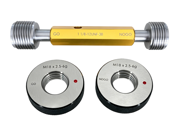
External thread inspection relies on tactile precision as much as dimensional accuracy. When checking threaded studs, bolts, or precision turned components, an operator’s manual technique directly influences whether a part passes or fails quality inspection. Applying too much force, tilting the tool off-axis, or misunderstanding acceptance thresholds can lead to scrapping functional parts or accepting out-of-spec products.
Mastering how to use thread ring gauges requires controlling three primary mechanical variables: maintaining true axial alignment during entry, limiting rotational torque to prevent artificial expansion, and applying the standard “number of turns rule” to differentiate between functional lead engagement and pitch diameter failure.
Implementing standard operating practices across these areas protects delicate measuring surfaces, avoids false non-conformance reports, and maintains traceability across production shifts.

Axial Alignment: Eliminating Cross-Threading and Initial Engagement Bias
Thread ring gauges check pitch diameter, lead, flank angles, and minor clearance simultaneously. Because ring gauges possess high thread contact area and tight tolerances, introducing the gauge at even a slight angular offset causes immediate interference.
When an inspector angles the gauge relative to the workpiece centerline, the crests of the gauge threads collide with the flanks of the component threads. This misalignment creates artificial resistance that mimics an oversized pitch diameter, prompting premature rejection. Continuing to rotate a misaligned gauge can gall the workpiece and permanently damage the gauge’s lead threads.
[ Gauging Axis ]
|
v
+—————————+ <– Thread Ring Gauge
| | | | | | | | | | | | |
+—| |-| |-| |-| |-| |-| |-+
| | | | | | | | | | |
============================= <– Workpiece Component
Centerline (0°)
Standard Alignment Procedure
Mount or Position Vertically When Feasible: If inspecting loose parts at an inspection bench, position the workpiece vertically in a soft-jaw fixture or hold it steady. Presenting the ring gauge perpendicular to the vertical axis lets gravity assist natural seating rather than pulling the tool out of alignment.
Engage with Counter-Rotation: Place the ring gauge squarely against the start of the external thread. Rotate the gauge backward (counterclockwise for standard right-hand threads) until you feel a distinct tactile drop or “click.” This drop signifies that the start thread of the gauge has aligned with the lead thread of the workpiece.
Advance Without Lateral Canting: Once seated, rotate clockwise using smooth, balanced rotational pressure. Keep your fingers equidistant on the knurled outside diameter to prevent cocking the gauge against the component axis.
Torque Guidelines: The Zero-Forced-Engagement Approach
A thread ring gauge is an inspection standard, not a sizing die or a threading tool. It must never be used to chase threads, shave burrs, or force compliance on marginal parts.
Applying excessive torque expands the ring gauge mechanically, temporarily opening its pitch diameter and allowing an out-of-spec part to pass. Conversely, forcing a stuck gauge binds the mating flanks, leading to metal-to-metal pickup, micro-galling, and gauge wear.
| Handling Factor | Standard Shop-Floor Practice | Risk of Non-Compliance |
| Grip Method | Two-finger or three-finger turn on knurled OD | Full-hand gripping creates excessive leverage |
| Torque Limit | Minimal hand torque (feathered rotational force) | Wrench or mechanical aid permanently deforms gauge |
| Encountering Resistance | Stop immediately; reverse gently and inspect | Forcing through binds flank surfaces and causes galling |
| Part Condition | Clean, dry or lightly oiled depending on standard | Heavy viscous grease masks dimensional drag |
The “Two-Finger” Rule
Operators should rotate thread ring gauges using light pressure between the index finger and thumb. If the gauge cannot be turned along the functional thread length using this degree of manual torque, the part does not conform to the required thread envelope. Never use wrenches, pliers, bench vises, or mechanical levers to drive a ring gauge. Sourcing certified precision thread gauges made from hardened, wear-resistant steels helps maintain dimensional stability under regular inspection conditions, but proper manual technique remains necessary to avoid premature tool replacement.
The “Number of Turns Rule”: Clear Standards for Go and No-Go Acceptance
Interpreting thread ring gauge engagement requires a clear distinction between the functional roles of the Go and No-Go members. While a Go gauge validates maximum material condition across the full engagement length, a No-Go gauge inspects minimum material condition by checking that the pitch diameter is not undersized.
+————————————————————————–+
| THREAD RING GAUGE DECISION MATRIX |
+——————-+——————————————————+
| GAUGE TYPE | ACCEPTANCE STANDARD |
+——————-+——————————————————+
| Go Gauge | Must freely pass over full thread length |
| | with light hand-torque and zero force. |
+——————-+——————————————————+
| No-Go Gauge | Must NOT fully engage the component. |
| (General Practice)| Allowed: Maximum 2 to 3 turns of partial engagement. |
+——————-+——————————————————+
| No-Go Gauge | Disengage and stop immediately if significant |
| (Critical Action) | resistance occurs within the 2–3 turn window. |
+——————-+——————————————————+
The Go Ring Gauge
The Go ring gauge must spin smoothly over the entire length of the specified external thread using light hand effort. If the Go gauge stops or binds at any point before reaching the final thread runout:
The major or pitch diameter is oversized.
There is lead error or taper along the length of the thread.
Root radii or thread flanks contain uncut material or chips.
The No-Go Ring Gauge and the 2–3 Turn Allowance
A common source of disagreement in thread inspection is the No-Go gauge engaging the first couple of threads. Machinists often assume that if a No-Go gauge turns at all, the part is scrap. However, established industrial standards—such as ASME B1.2 and ISO 1502—account for imperfect lead-in threads, chamfer runout, and manufacturing relief.
The General 3-Turn Guideline (ASME B1.2): A No-Go ring gauge is generally permitted to turn onto the component up to a maximum of three complete turns before coming to a definite stop.
The 2-Turn Limit (ISO 1502): Metric inspection standards often restrict this allowance further, generally stating that the gauge must not enter more than two complete turns. If the thread length is very short (e.g., three threads or fewer), entry beyond one turn may indicate non-conformance.
Functional Meaning: The partial turn allowance applies strictly to incomplete, chamfered start threads. If the gauge advances past this limit without definite resistance, the pitch diameter is below the minimum material limit, and the part must be rejected.
Pre-Inspection Cleanliness: Eliminating False Rejections
Foreign particles and thermal discrepancies routinely cause false rejections. Because thread pitch diameters operate within tight micron-level windows, microscopic contamination alters engagement feedback.
Burrs and Flash Removal: The thread crests and lead-in chamfer must be thoroughly deburred. A single raised rollover burr from a single-point turning tool can stop a Go gauge immediately, giving the false impression of an oversized pitch diameter.
Cleaning Fluid and Particulate Swarf: Fine chips, grinding grit, and dried coolant residue settle into thread roots. Wash parts with an evaporative cleaner and blow dry before testing. Thread ring gauges should be periodically cleaned with a soft brush and non-corrosive solvent to clear internal flutes and root reliefs.
Thermal Equilibrium: Thread ring gauges are calibrated at standard reference conditions (typically 20°C / 68°F). Testing hot components taken directly from a CNC machine bed introduces measurement error; thermal expansion can cause a conforming part to bind inside a Go ring gauge.
Troubleshooting Common Thread Ring Gauge Inspection Discrepancies
When a discrepancy arises on the shop floor, follow this systematic diagnostic framework to isolate the cause:
| Observed Symptom | Probable Cause | Actionable Remedy |
| Go gauge stops midway along thread | Component thread has taper, lead stretch, or poor pitch alignment | Check tool offset and lead accuracy on optical comparator; inspect for swarf in root |
| Go gauge binds only on entry | Rollover burr on lead-in chamfer; damaged entry thread | Rework lead-in chamfer to remove feather burr; ensure zero tool push-off at start |
| No-Go gauge enters >3 full turns | Pitch diameter undersized; machine tool offset pushed too far | Adjust radial tool offsets to add material; verify CNC tool nose radius wear |
| Gauge feels gritty during rotation | Contaminants or abrasive dust embedded in internal gauge threads | Solvent wash the gauge; use an ultrasonic bath if necessary; relubricate lightly |
| Inconsistent feel across identical parts | Operators applying inconsistent torque or axial tilting | Standardize inspection procedure using bench-fixed parts and two-finger torque |
| Discrepancy between two ring gauges | Gauge wear; pitch diameter calibration drift | Inspect ring gauge against calibrated master setting plugs |
Maintaining Calibration Integrity and Wear Limits
Thread ring gauges experience continuous friction during use. Without systematic wear tracking, abrasive shop-floor environments will eventually wear internal pitch diameters beyond acceptable limits.
Unlike thread plug gauges, solid or adjustable thread ring gauges cannot be measured directly with standard micrometers. They require calibrated master setting plugs (truncated Go and full-form No-Go setting plugs) for verification.
Store thread ring gauges in sealed compartments away from airborne moisture and grinding dust. After each production run or shift, wipe the working threads clean, coat them with a thin layer of acid-free rust preventive oil, and store them flat. When thread ring gauges fail verification against a setting plug or exhibit visible chipping on lead threads, remove them from the production floor immediately for calibration or replacement.
Standardizing Quality Control with Consistent Gauging Solutions
Precise thread quality control relies on using the right equipment and operating it correctly. By enforcing true axial alignment, eliminating heavy-handed torque, and adhering strictly to the 2-to-3 turn rule for No-Go members, manufacturers reduce rework and eliminate disputes over component fit.
For facilities producing critical threaded components, reliable dimensional verification starts with stable, certified thread gauges that conform to international manufacturing standards. Standardizing these handling practices ensures long tool life and dependable inspection results from the first part of a production run to the last.
Key Takeaways
Light Torque Standard: Thread ring gauges must only be turned by hand using two-finger rotational pressure. Mechanical tools must never be used to force engagement.
Alignment Precedes Rotation: Back-rotate the gauge until it seats cleanly into the lead thread before turning forward. This eliminates cross-threading and prevents premature tooth wear.
The Number of Turns Rule: A Go gauge must pass the full functional thread length without binding. A No-Go gauge is permitted a maximum of 2 to 3 turns of partial engagement on chamfered leads (subject to the governing standard) before coming to a complete stop.
Environment and Cleanliness: Clear all burrs, swarf, and coolant residue, and ensure parts cool down to ambient temperature before gauging to avoid false rejections.
Verification via Setting Plugs: Ring gauge wear cannot be evaluated by eye; periodically verify your thread ring gauges against calibrated master setting plugs.
FAQ
Why does a thread ring gauge stick on the first thread of a component?
A thread ring gauge usually binds on the first thread due to axial misalignment, a rolled-over deburring burr, or a damaged lead thread on the workpiece. Gently turn the gauge counterclockwise until it clicks into place before advancing, and ensure the part’s lead-in chamfer is clean and free of burrs.
Can I use cutting oil or lubricant while checking threads with a ring gauge?
Heavy cutting fluids and viscous oils should be removed prior to inspection, as they can hydraulically pack thread roots and mask tight fits. However, a light film of low-viscosity rust-preventive oil or non-gumming inspection lubricant is acceptable to minimize friction and prevent surface galling during manual testing.
What is the difference between ISO and ASME rules regarding No-Go ring gauge entry?
ASME B1.2 permits a No-Go thread ring gauge to engage up to a maximum of three complete turns if practical fit considerations require it, provided definite resistance is felt. ISO 1502 enforces a stricter limit, stating that the gauge should not enter more than two complete turns on components with more than three threads. Always consult the contract specification for the applicable standard.
How do I know if my thread ring gauge has worn out?
Because internal threads cannot be measured using standard vernier or external micrometers, ring gauges are checked using master thread setting plug gauges. If a Go ring gauge becomes loose on its calibrated Go setting plug, or if a No-Go ring gauge advances past the permitted limit on its corresponding setting plug, the ring gauge is out of specification and must be calibrated, adjusted, or replaced.