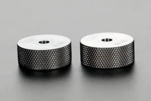
In CNC turning and milling operations, verifying tight-tolerance interior features quickly and accurately determines whether a production run stays on schedule. A pin gauge provides machinists and quality control inspectors with an immediate physical reference to verify hole boundaries, narrow slot widths, and center-to-center hole distances directly at the machine tool. Unlike optical comparators or touch-trigger coordinate measuring machines (CMMs)—which can create production bottlenecks or struggle with deep, micro-diameter bores—cylindrical pin gauges deliver fast, pass/fail tactile feedback.
Accurate inspection with pin gauges requires matching the gauge tolerance class to the workpiece print, accounting for thermal conditions, and applying correct measuring techniques to prevent gauge binding or premature wear. This technical guide outlines how to inspect internal diameters, verify milled slot widths, calculate hole centerline distances using mathematical offsets, and select the appropriate gauge specifications for precision CNC manufacturing.
The Role of Pin Gauges in CNC Machining Quality Control
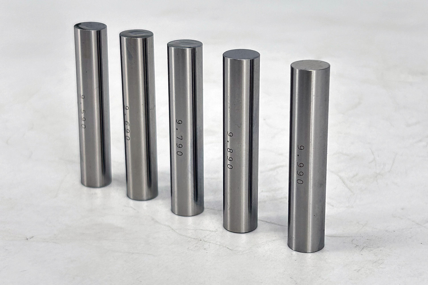
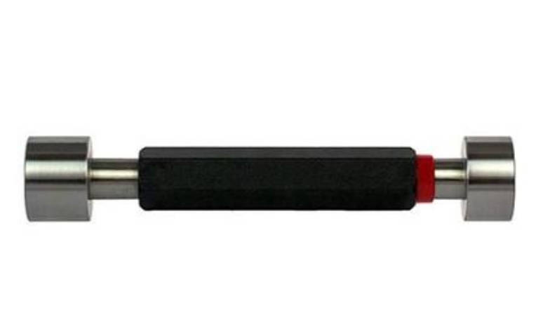
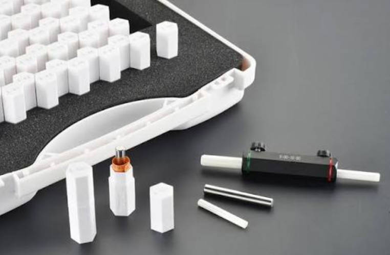
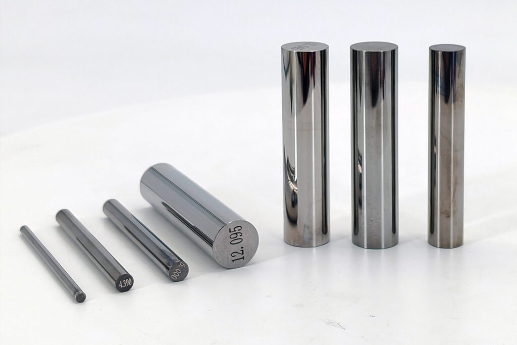
A pin gauge is a ground, hardened cylindrical tool made to a certified outside diameter used to check the size, geometry, and location of internal workpiece features. On the machine shop floor, checking bore diameters using vernier calipers often introduces user parallax and jaw alignment errors, especially on holes smaller than 3 mm (0.118 in). While three-point internal bore micrometers handle larger bores, they cannot measure very small bores or narrow keyways.
| Inspection Tool | Primary Advantage | Practical Limitation |
| Pin Gauge | Rapid, tactile go/no-go verification for small holes and narrow slots | Fixed step sizes; cannot quantify infinite variable dimensions within a step |
| Three-Point Bore Micrometer | Direct digital or vernier readout of absolute bore diameter | Limited availability for micro-holes below 2 mm; blind hole bottom limits |
| CMM (Coordinate Measuring Machine) | Automated multi-axis geometric dimensioning and tolerancing (GD&T) | Programming overhead; slow cycle times for 100% inline shop-floor verification |
Integrating pin gauges directly into production setups allows CNC operators to identify tool wear, deflection, or thermal drift on the roughing or finishing pass before defective parts accumulate in the bin.
Inspecting Internal Diameters: The Go/No-Go Method for CNC Bores
The standard shop-floor technique for checking hole tolerances is the limit gauge method, utilizing a go no-go pin gauge pair.
| Workpiece Feature | Target Nominal & Limits | Applied Gauge Size | Acceptance Criteria |
| Hole Lower Limit (Go) | Ø 6.000 mm (+0.000 mm) | Ø 6.000 mm | Must enter bore smoothly under light finger pressure across the entire depth |
| Hole Upper Limit (No-Go) | Ø 6.025 mm (+0.025 mm) | Ø 6.026 mm | Must not enter bore beyond the entry chamfer |
1. Setting Go and No-Go Limits According to Engineering Drawings
The Go Gauge: Sized to the lower specification limit (minimum material condition for an internal hole). The Go member must slide completely through the full length of the bore without binding when guided gently by hand.
The No-Go Gauge: Sized one increment above the upper specification limit (maximum material condition for an internal hole). The No-Go gauge must not engage the hole beyond the entry chamfer. If the No-Go gauge enters the bore, the feature is oversized and the part must be scrapped or reworked.
2. Detecting Geometry Errors: Bell-Mouth, Taper, and Out-of-Round Defects
Beyond simple diameter confirmation, a machinist can diagnose machining tool errors by reading the resistance of the pin gauge through the bore:
| Machining Defect | Physical Gauge Response | Root Cause on CNC Machine |
| Tapered Bore | Go gauge enters the hole mouth freely but binds halfway down the bore depth | Tool push-off, boring bar deflection, or uneven tool wear |
| Bell-Mouth Hole | Go gauge fits loosely at entry but locks tightly toward the middle and bottom | Excessive dwell time at hole entry, spindle/reamer runout, or coolant wash |
| Out-of-Round / Lobing | Gauge binds intermittently when rotated axially inside the hole | Excessive 3-jaw chuck clamping pressure causing bore distortion after unchucking |
Measuring Slot Widths, Keyways, and Groove Depths
Milled slots, O-ring channels, and internal keyways present measurement challenges because standard caliper depth blades or outside jaws often bottom out unevenly against draft angles and corner radii. Slot width measurement with pin gages eliminates edge-contact errors through progressive step-testing.
| Step Sequence | Pin Size Used | Action & Fit Condition | Diagnostic Conclusion |
| Step 1 | 3.95 mm | Enters freely across the entire slot length | Passes lower tolerance boundary |
| Step 2 | 4.00 mm | Smooth sliding fit along full travel | Confirms nominal slot condition |
| Step 3 | 4.05 mm | Snug fit; binds at isolated points | Identifies local pinch points or cutter deflection |
| Step 4 | 4.06 mm | Refuses entry at all slot positions | Confirms slot does not exceed upper tolerance limit |
Practical Rules for Slot Verification
Sweep the Full Length: Slide the pin gauge along the entire linear path of the slot. Localized tightening indicates tool deflection, machine table backlash, or workpiece warping caused by internal stress relief during milling.
Radial Clearance Considerations: Ensure that the corner radius generated by the end mill does not interfere with the outer boundary of the cylindrical pin gauge during depth checks.
Verifying Hole Center Distances and Position Alignment
Coordinate measuring machines are the conventional standard for true-position tolerance inspection, but machinists can carry out reliable intermediate checks on hole center-to-center spacing using two pin gauges and a digital vernier caliper.
| Measurement Parameter | Symbol | Definition & Function |
| Pin 1 Diameter | $D_1$ | Calibrated outside diameter of the gauge seated in Hole 1 |
| Pin 2 Diameter | $D_2$ | Calibrated outside diameter of the gauge seated in Hole 2 |
| Span Over Pins | $M$ | Maximum outer distance measured across both installed pins |
| Span Between Pins | $I$ | Minimum inner distance measured between the interior walls of both pins |
| Calculated Center Pitch | $C$ | True centerline distance between the two hole centers |
The Two-Pin Calculation Method
Insert a snug-fitting pin gauge into each of the two machined holes. Choose the largest pin diameter that enters each hole without mechanical force to minimize radial play.
Record the exact certified diameter of Pin 1 ($D_1$) and Pin 2 ($D_2$).
Using the flat outside jaws of a calibrated caliper or depth micrometer, measure the maximum span over the outer diameter of both installed pins ($M$).
Calculate the center-to-center pitch distance ($C$) using the formula:
$$C = M – \left(\frac{D_1}{2} + \frac{D_2}{2}\right)$$
Simplified formula when both holes and pins share identical diameters ($D_1 = D_2 = D$):
$$C = M – D$$
Alternative Measurement (Inside Distance): If measuring between the inner faces of the pins using caliper inside jaws ($I$):
$$C = I + \left(\frac{D_1}{2} + \frac{D_2}{2}\right)$$
This comparative inspection method enables machine operators to verify hole spacing across bolt patterns, dowel locations, and manifold ports without removing the part from the machining fixture.
Choosing the Right Pin Gauge Class and Material
Selecting the appropriate pin gauge requires balancing the tolerance window of the machined component against tool wear resistance and gauge manufacturing standards. Industrial pin gauges are graded under standard tolerance classes, notably governed by standards such as ANSI/ASME B89.1.5.
| Gauge Class | Diameter Tolerance (≤ 0.825 in / 21 mm) | Typical CNC Machining Application |
| Class XX | 0.0005 mm (0.000020″) | Calibration master labs; aerospace critical sub-micron bore verification |
| Class X | 0.0010 mm (0.000040″) | Precision CNC toolroom, high-end mold components, and tight press-fits |
| Class Y | 0.0018 mm (0.000070″) | General machining inspection with moderate drawing tolerances |
| Class Z | 0.0025 mm (0.000100″) | Production roughing; commercial parts with standard limits |
| Class ZZ | 0.0050 mm (0.000200″) | High-wear shop-floor pass/fail checks; general loose-tolerance bores |
Plus (+) vs. Minus (-) Tolerance Direction
| Tolerance Direction | Manufacturing Dimension Bias | Typical Gauge Role | Purpose & Protection |
| Plus (+) Tolerance | Nominal to +Tolerance (e.g., +0.005 mm / -0.000 mm) | Go Member | Guarantees hole is not smaller than print; provides wear allowance |
| Minus (-) Tolerance | Nominal to -Tolerance (e.g., +0.000 mm / -0.005 mm) | No-Go Member | Guarantees hole is not larger than print; prevents accepting oversize parts |
Material Selection Comparison
| Material Type | Typical Hardness | Wear Resistance Factor | Corrosion Resistance | Primary Use Case |
| Hardened Tool Steel (GCr15 / 52100) | 60–62 HRC | 1x (Baseline standard) | Low (Requires oil barrier) | General shop-floor toolroom checks; economical |
| Tungsten Carbide | 89–92 HRA | 8x – 10x vs. Tool Steel | High | High-volume production; cast iron, high-silicon aluminum |
| Ceramic (Zirconia) | >1000 HV | 5x – 8x vs. Tool Steel | Complete immunity (Inert) | Cleanrooms, non-magnetic parts, stainless steel anti-galling |
Best Practices for Shop-Floor Handling, Maintenance, and Thermal Compensation
Small measuring errors compound quickly when handling micro-inch and micron-level metrology equipment.
| Operational Factor | Inspection Risk | Recommended Standard Practice |
| Thermal Expansion | Steel expands at $\approx 11.5 \times 10^{-6} / ^\circ\text{C}$; warm pins yield false rejections | Stabilize both gauge and workpiece at 20°C (68°F) before critical checks |
| Insertion Force | Forcing pins galls part surfaces and scores reference gauge OD | Guide pins strictly by finger weight; never hammer or drive into bore |
| Part Cleanliness | Chips, dust, and dried coolant film register false undersized readings | Blow out bores with dry air and clean with lint-free solvent wipes |
| Calibration Drift | Continuous friction causes gauge taper and undersized Go members | Audit high-use pins on a regular schedule using laser micrometers |
Sourcing Precision Gauges for Machining Operations
For custom CNC manufacturing, relying solely on off-the-shelf standard step sets often leaves measurement gaps in stepped-hole geometries, proprietary oil ports, or custom internal chamfers. Technical procurement teams evaluating a dedicated pin gauge manufacturer like Mihe should establish clear design and inspection parameters before placing volume orders:
| Sourcing Parameter | Recommended Technical Specification to Confirm |
| Tolerance Class | Class X or Class ZZ, verified to ASME B89.1.5 or ISO equivalence |
| Increment Steps | Standard 0.01 mm steps or custom micro-steps (0.005 mm / 0.002 mm) |
| Substrate Material | GCr15 bearing steel, solid tungsten carbide, or zirconia ceramic |
| Quality Verification | NIST-traceable, CNAS-accredited, or factory inspection certificates |
| Surface Finish | Ground and lapped to micro-finish specifications ($R_a \le 0.1\ \mu\text{m}$) |
Key Takeaways
Primary Function: Pin gauges provide rapid, repeatable Go/No-Go inspection for small holes, narrow slot profiles, and hole-to-hole center locations where electronic probes and caliper blades struggle.
Geometry Diagnostics: Variations in drag resistance as a pin moves down a bore reveal common machining defects like tapers, bell-mouth openings, and chuck-induced lobing.
Center-to-Center Positioning: Two pin gauges inserted into adjacent holes enable accurate hole-pitch calculations using the over-pins measurement formula: $C = M – \frac{D_1 + D_2}{2}$.
Tolerance Matching: Class X tolerances are suited for precision tooling and tight-tolerance CNC bores, while Class ZZ serves standard pass/fail applications. Plus (+) configurations are designated for Go gauges and Minus (-) for No-Go gauges.
Temperature Stability: Metrology inspection should take place after the workpiece and gauge have thermally equalized at standard reference room temperatures (20°C / 68°F).
FAQ: Frequently Asked Questions
Can pin gauges be used to inspect blind holes accurately?
Yes, but with limitations. Standard pin gauges verify the entrance and body diameter of a blind hole. However, they cannot inspect the very bottom of the feature if the hole ends in a drill point angle or an internal corner radius. For full-depth blind hole checks, flat-faced or bottoming plug gauges are required.
What is the difference between a plus (+) and minus (-) pin gauge?
A plus gauge has its allowable manufacturing tolerance applied entirely on the positive side of nominal, making it equal to or slightly larger than the marked size. A minus gauge has its tolerance applied on the negative side, making it equal to or slightly smaller than marked. In basic limit gauging, Go members use plus tolerances and No-Go members use minus tolerances.
How do temperature fluctuations in the CNC workshop affect gauge measurements?
Because metals expand with heat and contract with cold, checking warm parts straight off a machine spindle using cold pin gauges introduces significant measurement error. For sub-micron or tight Class X tolerances, both the workpiece and the pin gauges must stabilize at 20°C (68°F) before taking final measurements.
What should I do if a pin gauge becomes stuck in a machined bore?
Never hammer the pin or use vice pliers on its ground reference surface. Apply a penetrating oil to the interface and allow it to soak. If thermal binding caused the seizure, cool the assembly or apply mild localized warmth to the outer workpiece while keeping the pin cool, then withdraw the gauge along its true linear axis.