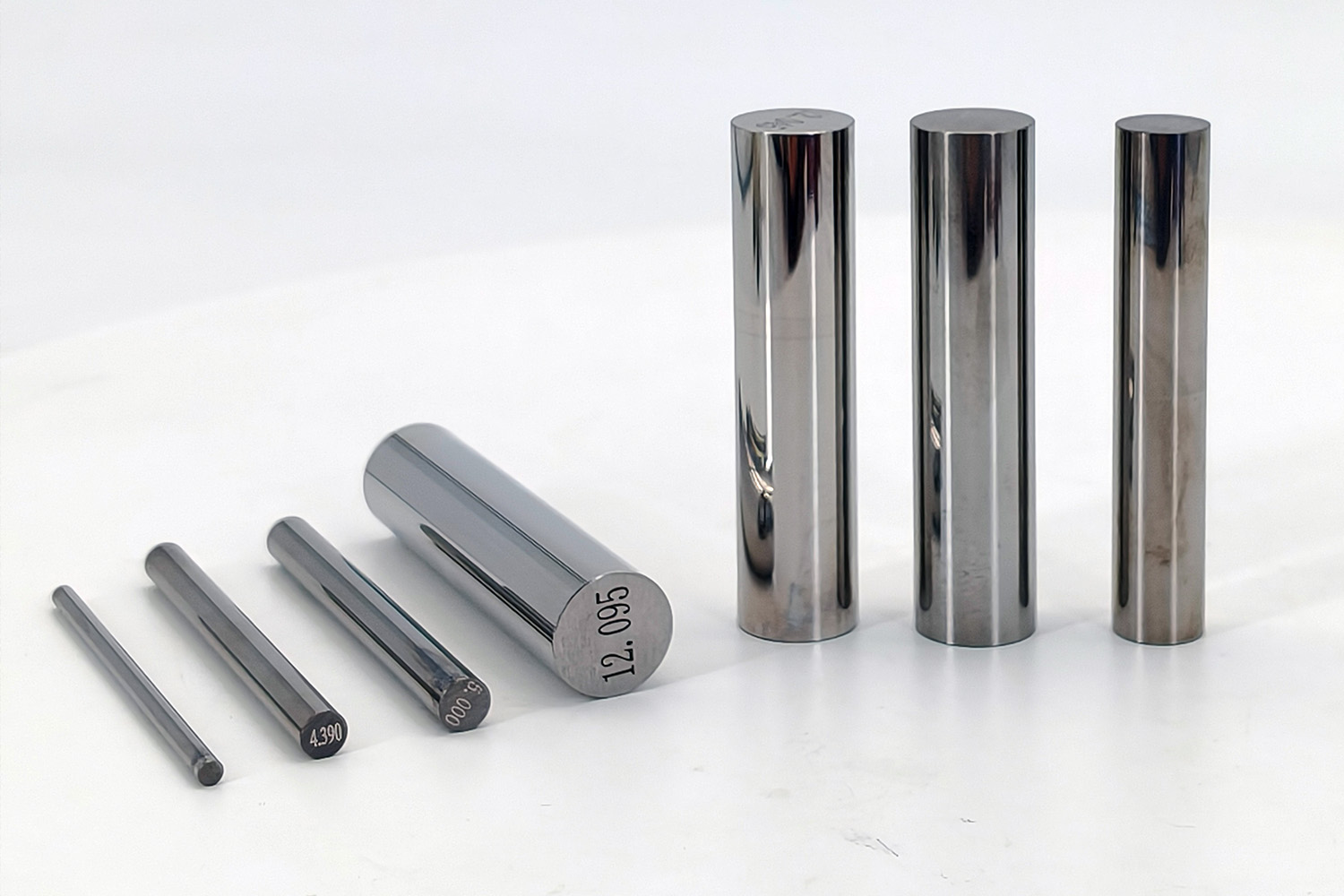
Ordering custom pin gauges requires far more detail than specifying a nominal diameter. When engineering teams submit requests showing only a target size like “6.35 mm,” manufacturers cannot determine the manufacturing tolerance, thermal behavior, or surface profile required for your inspection routine. To quote accurately and manufacture parts that pass quality control on the first delivery, a supplier needs six defined criteria: physical dimensions, tolerance class and direction, material grade, geometric profiles, surface finish, and certification requirements.
This guide outlines the exact parameters quality engineers and procurement specialists must confirm before submitting a request for quotation (RFQ), preventing costly production revisions and inspection discrepancies.
The Cost of Ambiguity: Why Incomplete Specs Delay Custom Pin Gauge Orders
In precision metrology, ambiguity creates scrap. When an RFQ omits tolerance directions or material constraints, a manufacturer must either halt the quotation process for technical clarification or make baseline assumptions that may not match your inspection environment.
| Procurement Stage | Impact of Incomplete RFQ (e.g., “5.0 mm Pin Gauge”) | Operational Consequence |
| Initial Review | Missing tolerance direction, material grade, or surface specs | Engineering inquiry flagged; design review suspended |
| Quotation Cycle | Technical clarification emails and dimensional back-and-forth | Quote generation delayed by 24 to 72 hours |
| Production & Receipt | Manufacturer builds to default baseline rather than application limits | High risk of non-conforming tooling and failed incoming QA audits |
A pin gauge manufactured without explicit functional parameters risks failing internal tool audits or providing false acceptance on the shop floor. Defining your operational requirements upfront ensures the finished tool meets your measurement criteria directly from the box.
1. Dimensional & Tolerance Specifications: The Non-Negotiable Basics
Dimensional specifications establish the physical envelope and boundary conditions of the gauge.
Nominal Diameter, Overall Length, and Dual-End Limits
Specify dimensions in either metric units (millimeters) or imperial units (inches), avoiding mixed units within the same drawing set. Standard catalog gauges generally come in fixed increments and lengths (often 50 mm or 2 inches), but custom jobs can vary significantly:
Nominal Outer Diameter (OD): State the precise decimal target (e.g., 4.215 mm).
Overall Length (OAL): Specify whether standard gauging depth is sufficient or if deep-bore inspection requires extra reach.
Functional Step Dimensions: If requesting a stepped pin gauge to test two hole depths or stepped IDs simultaneously, supply a dimensioned 2D print detailing transition steps.
Tolerance Class and Direction (Plus, Minus, or Bilateral)
Diameter alone does not govern manufacturing. You must specify the allowable variation limit. Pin gauge tolerances often reference standard metrology classifications (such as Class ZZ, Class Z, Class X, or Class XX) or explicit numerical bands (such as $\pm 0.001\text{ mm}$ or $+0.002/-0.000\text{ mm}$).
| Tolerance Direction | Functional Application | Manufacturing Result |
| Plus Tolerance (+) | Standard “Go” plug gauging | Gauge is never smaller than nominal size; ensures minimum hole clearance. |
| Minus Tolerance (-) | Standard “No-Go” plug gauging | Gauge is never larger than nominal size; catches oversized holes. |
| Bilateral Tolerance ($\pm$) | Master setting pins / Calibration | Tolerance splits evenly across nominal dimension. |
When configuring standard and custom plug gauges, always clarify if your stated limits represent the total allowable band or a one-directional limit.
2. Material Grade & Hardness: Matching Durability to Your Inspection Environment
The material of your pin gauge dictates dimensional stability, wear life, and corrosion vulnerability. Selecting the proper substrate depends directly on how often the gauge is used and the abrasive properties of the parts being inspected.
| Substrate Material | Typical Applications | Wear Life & Resistance | Key Considerations |
| Tool Steel / Bearing Steel (e.g., GCr15 / 52100) | Standard toolroom spot checks and moderate-volume QA routines | Moderate wear resistance; typical heat-treated hardness of 60–62 HRC | Economical baseline; requires anti-rust oil in humid environments |
| Tungsten Carbide | High-volume production lines checking abrasive cast iron, alloys, or composites | High wear resistance; retains critical dimensions significantly longer | Higher initial cost; brittle substrate susceptible to chipping if dropped |
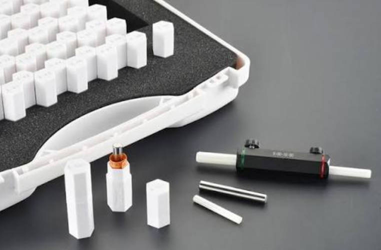
| Technical Ceramics (Zirconia / Alumina) | Corrosive environments, cleanrooms, and non-magnetic electrical assemblies | Zero metallic transfer; impervious to rust and acid degradation | Low thermal expansion; non-conductive; avoids cold welding to non-ferrous parts |
Note: Specific hardness levels and alloy options should be confirmed against supplier machining capabilities and application requirements.
3. Critical Geometry Details Often Overlooked in Drawings
Beyond basic diameter and material, secondary mechanical features dictate how smoothly the pin engages with the part and how reliably it resists mechanical stress.
Surface Finish & Roundness Requirements
A low-friction surface finish prevents premature wear and reduces galling when inserting pins into tight-tolerance bores:
Surface Roughness ($R_a$): Specify maximum allowable roughness. Precision inspection pins typically target an $R_a$ between 0.05 and 0.2 $\mu\text{m}$, achieved through precision cylindrical grinding and micro-lapping.
Roundness and Cylindricity: If a pin gauge is out-of-round, it will yield inconsistent measurement readings depending on how the inspector rotates the tool in the bore. Ensure your tolerance callout accounts for circularity limits.
Chamfer Angles and End Configurations
Pins without configured ends will burr or scratch inspected workpieces:
Spherical / Radius Ends: Facilitate smooth blind-hole entry and reduce alignment errors during manual checks.
Beveled / Chamfered Ends: Typical $15^\circ$ to $45^\circ$ lead chamfers guide the pin into through-holes without snagging internal threads or micro-burrs.
Marking, Handles, and Assembly Styles
Indicate whether pins should be delivered as individual loose pins or assembled with mechanical components:
Laser Etching: Specify required markings, such as nominal size, directional tolerance (+/-), tool serial number, or internal tool crib ID.
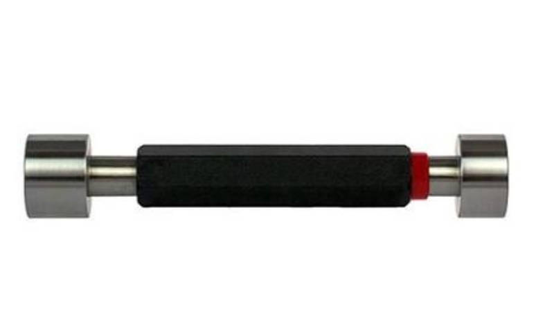
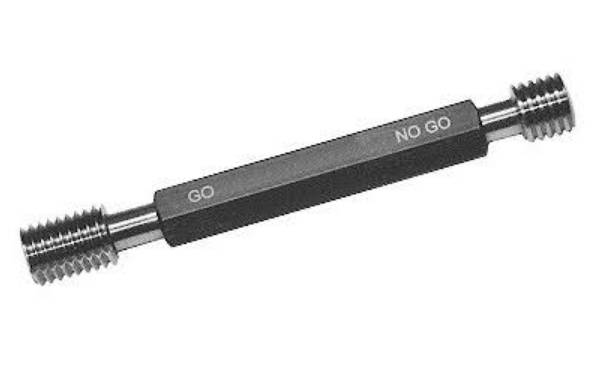
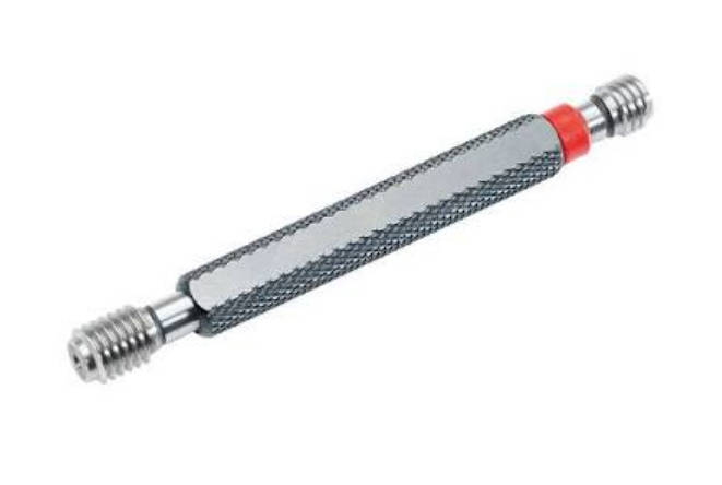
Handle Configurations: Indicate whether the pins require reversible collet-type handles, trilock handles, or hexagonal double-ended Go/No-Go assemblies.
4. Quality Certification & Traceability: What Documentation Do You Require?
A pin gauge is only as dependable as the documentation supporting its calibration. Manufacturing inspection standards vary, so documentation tiers must be stated during the initial inquiry:
Standard Factory Inspection Sheet: Verifies that the pin was measured internally and passed dimension checks prior to dispatch.
NIST-Traceable or ISO/IEC 17025 Accredited Calibration Reports: Required when pin gauges serve as master calibration tools or when parts are audited under aerospace, medical, or automotive quality regimes (e.g., AS9100, IATF 16949). These certificates detail actual measured dimensions, room temperature during testing, measurement uncertainty, and calibration instrument traceability.
Material Test Reports (MTR): Confirms chemical composition, heat-treatment cycles, and core hardness if regulated by contract.
Custom Pin Gauge Procurement Checklist (Copy & Paste for RFQ)
Use this structured format when compiling your technical specifications for inquiry submission:
| Parameter | Required Specification | Example Entry |
| Nominal Diameter | Numerical value + Units | 8.125 mm |
| Length | Total overall length | 50 mm |
| Tolerance Limit | Class, numeric deviation, and direction | +0.001 mm / -0.000 mm |
| Substrate Material | Material grade or general type | Steel |
| End Style | Entry profile configuration | Dual-end 30° chamfer |
| Surface Roughness | Maximum allowable $R_a$ | Ra ≤ 0.1 µm |
| Handle / Assembly | Loose pin or specific handle type | Double-end Go/No-Go handle |
| Marking Requirements | Laser text to be etched on body | Size |
| Documentation Level | Required calibration verification | ISO/IEC 17025 Traceable Certificate |
| Order Quantity | Individual units or matched pairs | 10 matched pairs |
Streamline Your Custom Pin Gauge Sourcing with Mihe
Eliminating guesswork from pin gauge procurement protects your machining tolerances and avoids supplier back-and-forth. By defining the diameter, tolerance direction, material grade, and certification up front, you ensure your tooling arrives production-ready.
When preparing your next tooling package, work directly with a certified pin gauge manufacturer capable of holding tight grinding limits across varied materials. Submit your technical drawings and specification checklist to the engineering team at Mihe for an application-specific review and production quotation.
Key Takeaways
Tolerance direction is critical: A 5.0 mm pin gauge manufactured with a plus tolerance acts as a Go gauge, while a minus tolerance creates a No-Go gauge. Specifying the sign ($+$, $-$, or $\pm$) is mandatory.
Material dictates application life: Bearing steel suits standard shop floor spot-checks, tungsten carbide resists abrasive high-volume manufacturing, and ceramics provide zero-corrosion, non-conductive stability.
Micro-geometry matters: Specifying lead chamfers, roundness limits, and an $R_a \le 0.2\,\mu\text{m}$ surface finish prevents hole scratching and insertion galling.
Documentation must align with audit needs: Specify whether you need standard factory inspection sheets or formal ISO/IEC 17025 traceable calibration certificates before production begins.
Frequently Asked Questions (FAQ)
What is the primary difference between custom pin gauges and custom plug gauges?
The terms are often used interchangeably in commercial requests, but structural differences exist. Pin gauges generally refer to cylindrical, uniform-diameter pins without integrated handles, used directly or placed in collet handles. Plug gauges typically refer to finished, handle-mounted assemblies often configured with dedicated Go and No-Go members on opposite ends.
Can custom pin gauges be ordered in stepped or non-cylindrical configurations?
Yes. Custom manufacturing can include stepped profiles to test multiple counterbore depths simultaneously, vented flats to allow air escape in blind holes, or radius tips for contoured part verification. These requests require detailed 2D CAD drawings indicating step transitions and concentricity tolerances.
How does ambient temperature affect custom pin gauge specifications?
Metrology standards calibrate pin gauges at $20^\circ\text{C}$ ($68^\circ\text{F}$). If your quality inspection room operates at non-standard temperatures, materials with different thermal expansion coefficients (like steel versus carbide) will expand or contract at different rates, potentially altering measurement results at sub-micron levels.
What file formats should accompany a custom pin gauge RFQ?
Vector PDF drawings showing all dimensional tolerances, geometric dimensioning and tolerancing (GD&T) callouts, and notes are standard. For stepped, threaded, or complex contour pins, accompanying 3D models (such as STEP or IGES files) ensure accurate machine programming.