A CNC-machined part can leave the machine looking correct and still contain a hole that is undersized, a slot that is too narrow, or a hole pattern that will not assemble with the mating component.
Pin gauges provide CNC shops with a fast way to check many of these features without obtaining a numerical measurement every time.
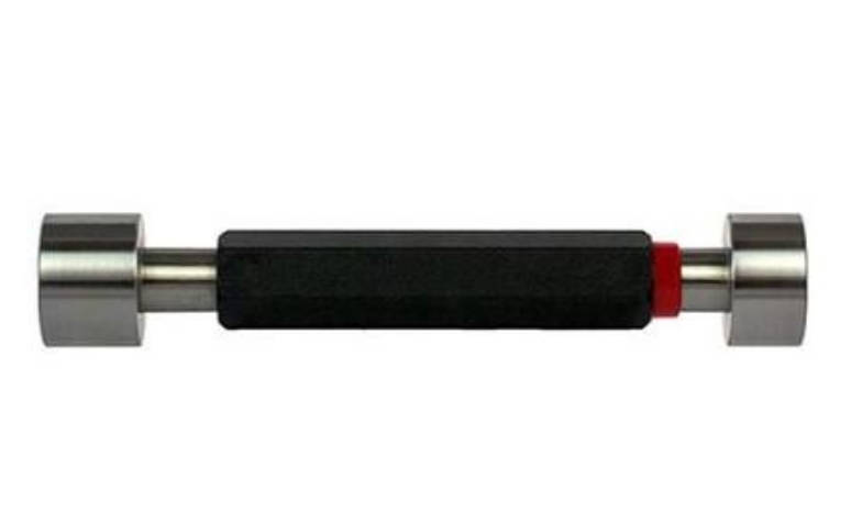
For CNC hole inspection, pin gauges are most effective as fixed-size acceptance tools: a selected pin either enters the feature or it does not.
They are particularly useful for:
- Drilled and reamed hole inspection
- GO/NO-GO bore checks
- Small-diameter feature verification
- Certain slot-width checks
- Hole-to-hole relationship checks when combined with another measurement method
- Functional fixture inspection of hole patterns
However, different applications require different gauging logic.
A pin that checks hole diameter does not automatically verify true position, and a cylindrical pin used in a slot does not provide the same information as a complete variable-width measurement.
The practical question for a CNC shop is therefore not simply:
“Can I use a pin gauge?”
It is:
“What decision do I need the pin gauge to make?”
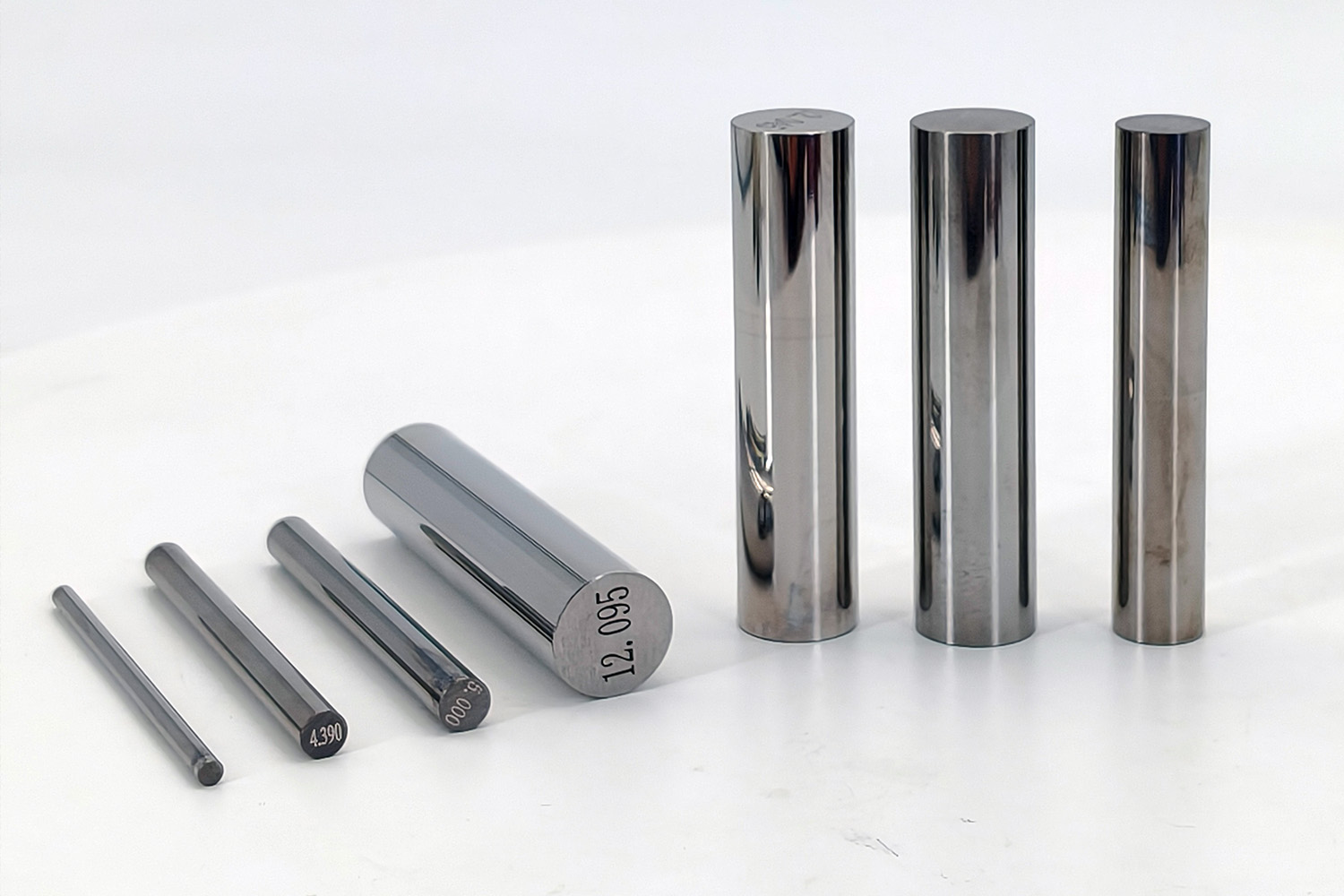
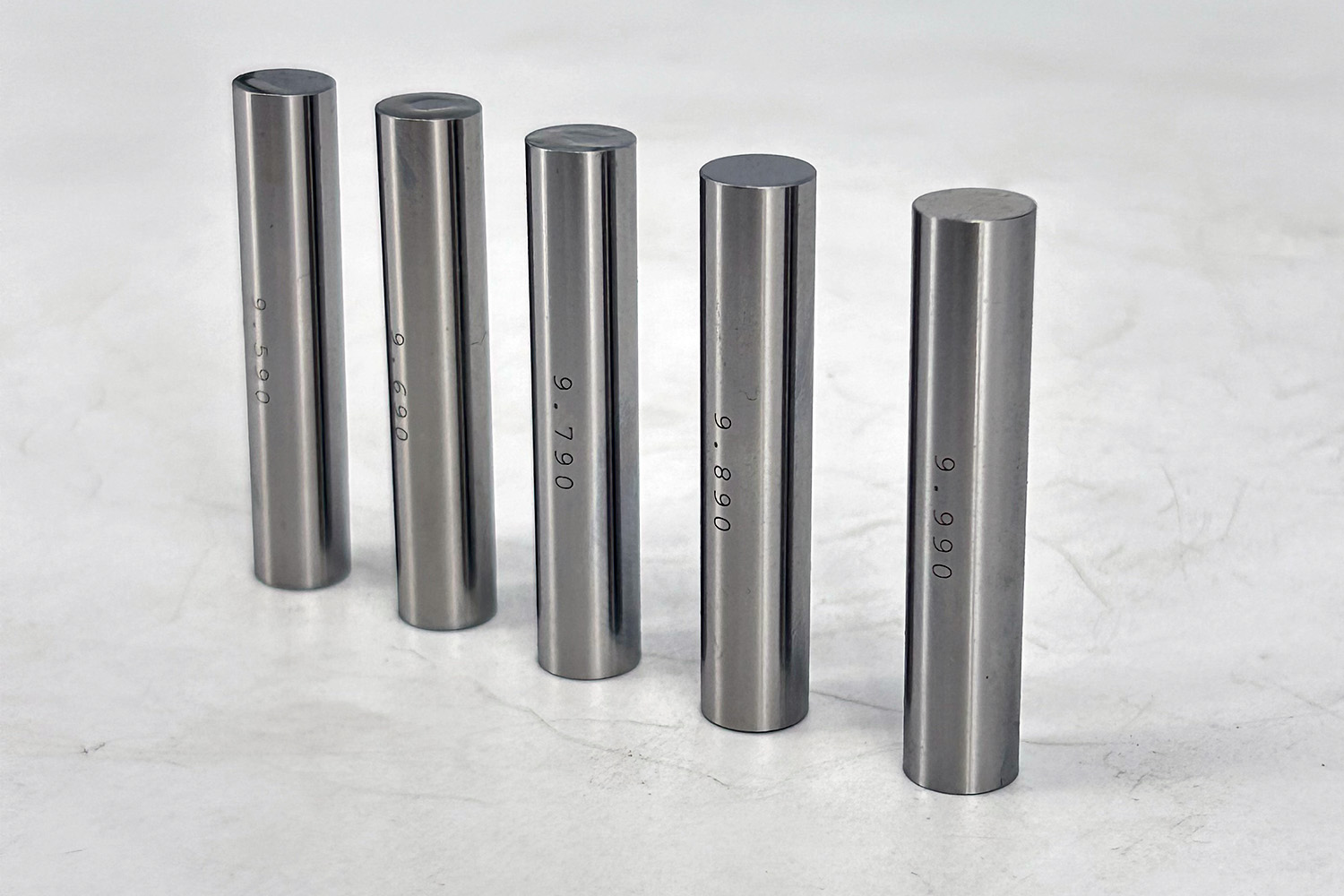
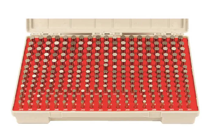
MISHUTE supplies precision pin gauges for CNC inspection in steel, zirconia ceramic, and tungsten carbide, with individual pins, sets, GO/NO-GO configurations, and customized dimensions available for different production requirements.
Inspection Station 1: A Reamed Hole Comes Off the Machine
Consider a CNC part with a precision reamed hole.
The drawing specifies:
Ø8.000–8.010 mm
The operator does not necessarily need to know whether the actual diameter is 8.004 mm or 8.006 mm on every part.
For production acceptance, the immediate questions may simply be:
- Is the hole at least 8.000 mm?
- Has it exceeded 8.010 mm?
This is a natural application for GO/NO-GO pin gauging.
The GO Pin
The GO pin represents the condition that the hole must accept.
If the required GO pin cannot enter under the defined inspection method, the hole may be undersized or affected by another condition such as:
- Burrs
- Chips
- Taper
- Local deformation
- Poor surface condition
- Incorrect tool offset
- Reamer wear or machining error
The NO-GO Pin
The NO-GO pin represents the opposite size limit.
If a pin representing the prohibited oversize condition enters when it should not, the feature may be outside its specified size tolerance.
A GO/NO-GO pin gauge turns a dimensional tolerance into a rapid pass/fail production decision.
ISO 1938-1 defines plain limit gauges, including cylindrical plug-type gauges, as dimensional measuring equipment used to verify linear-size limits.
For CNC shops performing repetitive checks, Go No-Go pin gauges can therefore reduce the need to obtain and interpret a numerical reading for every workpiece.
Why CNC Shops Use Pins Instead of Measuring Every Hole Numerically
A bore gauge, internal micrometer, CMM, or air gauge can provide more measurement information.
So why use pin gauges?
Because production inspection does not always require more information.
Suppose an operator needs to inspect 100 machined parts.
If the process requirement is simply to identify whether each hole remains inside its acceptable size limits, a fixed gauge can simplify the inspection to:
Accept / Reject
rather than:
Measure → Read → Interpret → Compare with drawing → Decide
This can be useful for:
- In-process checks
- Operator self-inspection
- Incoming inspection
- Final quality gates
- Tool-wear monitoring by periodic gauge checks
- Sorting parts after a suspected machining issue
Pin gauges are therefore attribute gauges rather than full process-analysis instruments.
They tell you whether a condition has crossed a limit; they do not normally tell you how far the machining process has moved toward that limit.
When a Pin Passes but the Hole Is Still Wrong
This is where CNC inspection becomes more interesting.
A cylindrical pin entering a hole does not prove that every geometric characteristic of that hole is acceptable.
Imagine a hole with:
- Taper
- Bell-mouth
- Barrel shape
- Poor roundness
- Mislocation
- Axis-angle error
A pin gauge may reveal some severe form problems because the pin physically cannot enter, but its primary role remains size-based functional checking.
A pin gauge can confirm a size condition without providing a complete map of hole geometry.
If the drawing separately controls:
- Cylindricity
- Circularity
- Perpendicularity
- Position
- Runout
- Surface finish
additional measurement methods may be necessary.
This is why pin gauges work particularly well as part of a CNC inspection system rather than as a replacement for every other measuring instrument.
Inspection Station 2: The Drawing Calls Out a Narrow Slot
Now consider another CNC part.
Instead of a round hole, it contains a machined slot with two nominally parallel walls.
Can a pin gauge check it?
In many practical situations, yes—but the inspection question must be defined carefully.
Using a Pin as a Width Limit Check
A cylindrical pin of a known diameter can be introduced between the slot walls.
If the pin representing the minimum acceptable slot width cannot enter, the slot may be too narrow.
A larger pin can also be used as a limit check where the inspection method and slot geometry make this appropriate.
This can be convenient for:
- Narrow milled slots
- Small precision gaps
- Recesses that are difficult to access with conventional calipers
- Production sorting
- Simple clearance verification
However, a cylindrical pin contacts the slot differently from a flat-ended width measuring instrument.
It should not automatically be treated as a complete measurement of the entire slot.
What a Pin May Miss
A slot may have:
- Non-parallel walls
- Taper along its depth
- Local cutter marks
- Edge burrs
- Corner radii
- Width variation along its length
A pin inserted at one location provides information about that local fit condition.
It does not necessarily prove that every point along the slot has the same width.
Use pin gauges for slot width when the required inspection is a clearly defined limit or functional check; use a suitable variable measuring method when an actual width profile is required.
This distinction prevents a fast production gauge from being asked to provide information it was never designed to produce.
Slot Width: Three Different Inspection Questions
Before selecting the gauge, identify the real question.
| Inspection Requirement | Pin Gauge Suitable? | Better Approach |
| Is the slot narrower than the minimum allowed width? | Yes, in many geometries | GO pin |
| Has the slot exceeded a defined upper functional limit? | May be suitable | NO-GO pin or custom gauge |
| What is the actual slot width? | Limited | Caliper, micrometer, CMM or other variable method |
| Are both walls parallel? | No, not by itself | Variable/geometric measurement |
| Is slot depth correct? | No | Depth measurement |
| Is slot location correct? | Not by itself | Datum-based positional measurement |
This is a useful procurement distinction.
If a factory only needs rapid part sorting, a simple gauge may be enough.
If the quality report must contain actual measured dimensions, pin gauging alone will not provide them.
Inspection Station 3: Two Holes Must Line Up During Assembly
The third application is often misunderstood.
Suppose a CNC plate contains two holes that must align with two mounting pins on another component.
Both hole diameters pass inspection.
But the parts still will not assemble.
The problem may be hole position.
Can you check this using pin gauges?
Yes—but not by simply inserting one pin into one hole and declaring the position correct.
A Single Pin Does Not Establish True Position
Geometric position is defined relative to the drawing’s basic dimensions and applicable datum reference framework.
A pin inserted in one hole provides a physical representation of that feature’s axis, but without a reference it does not tell you whether that axis is located correctly.
For example, you might insert precision pins into two holes and then measure:
- Distance between pins
- Distance over pins
- Pin-to-edge relationship
- Pin-to-datum fixture relationship
In this case, the pins act as physical measuring elements that make an otherwise inaccessible hole axis easier to reference.
But the complete measurement still requires another dimensional relationship.
Functional Position Gauging
A different approach is to build a functional fixture containing gauge pins positioned according to the drawing requirements.
The workpiece is placed against the required datum simulators, and the gauge pins attempt to enter the holes simultaneously.
If the part fits the fixture according to the applicable GD&T requirements, the gauge can provide a rapid functional acceptance decision.
ASME examples of positional functional gauging use gauge pins located at the required true positions to check hole patterns and their functional boundaries.
Pin gauges can support hole-position inspection, but true position requires a datum-based measurement or a correctly designed functional gauge—not an isolated diameter pin.
This distinction is important for CNC suppliers producing:
- Bolt-hole patterns
- Dowel-hole patterns
- Alignment plates
- Fixtures
- Housings
- Mating machined components
Hole Size Check vs Hole Position Check
These two inspection tasks are easy to confuse.
| Feature Requirement | What Is Being Controlled? | Role of Pin Gauge |
| Hole diameter | Size | Direct GO/NO-GO checking |
| Hole roundness | Form | Limited indication only |
| Hole position | Location relative to datums | Requires fixture or additional measurement |
| Hole-to-hole spacing | Relative location | Pins can provide reference surfaces for measurement |
| Pattern assembly | Functional relationship | Multiple fixed pins can be used in a functional gauge |
| Hole perpendicularity | Orientation | Pin may support measurement, but cannot establish it alone |
A CNC inspection plan should separate these requirements instead of treating the hole callout as one single characteristic.
Pin Gauges Are Particularly Useful Between Machining Operations
Pin gauges do not need to be reserved for final inspection.
They can be placed directly into the machining control loop.
Imagine the following process:
Drilling → Reaming → Operator Pin Check → Continued Production → Final QC
The operator checks the hole periodically using a selected working pin.
If the GO pin becomes increasingly difficult to insert, that can act as an early signal to investigate:
- Tool wear
- Tool offset
- Coolant conditions
- Chip evacuation
- Reamer condition
- Machine behavior
The pin does not identify the cause.
But it can tell the operator that the process is approaching or crossing an acceptance condition.
This makes pin gauges for precision machining useful not only for final QC but also for fast process feedback.
Do Not Force a Pin Into a CNC-Machined Hole
A gauge pin is an inspection tool.
It is not:
- A deburring tool
- A reamer
- A burnishing pin
- A press-fit installation tool
If a pin requires excessive force, stop.
Possible causes should be investigated before the gauge is pushed further.
Forcing a precision pin may:
- Damage the gauge
- Scratch the workpiece
- Remove a burr and hide the original condition
- Produce an inconsistent pass/fail decision
- Accelerate gauge wear
The gauge should be introduced squarely and using a consistent inspection method appropriate to the tolerance and application.
When You Need Individual Pins Instead of a Full Set
A full set is not always the most economical purchasing choice.
Consider a production line making only three critical hole sizes.
The quality department may need:
- GO pin for Size A
- NO-GO pin for Size A
- GO pin for Size B
- NO-GO pin for Size B
- GO and NO-GO pins for Size C
Individual working pins may be more practical than buying a large complete set.
This is especially true when the gauges will remain at one machine or inspection station.
Full Sets Make More Sense When
- The shop handles many different components
- Prototype work changes frequently
- Inspection dimensions vary every week
- The toolroom supports several machining cells
- Engineers frequently need intermediate sizes for troubleshooting
MISHUTE’s current product range supports individual pins, GO/NO-GO configurations and complete kits, along with standard and custom dimensional options.
GO/NO-GO Handles Can Improve Production Inspection
Loose pins are flexible, but repeated high-volume inspection can benefit from handled gauges.
A handled configuration can help operators:
- Identify GO and NO-GO members quickly
- Avoid touching measuring surfaces excessively
- Keep paired gauges together
- Reduce selection mistakes
- Improve repetitive handling
For dedicated production lines, a custom GO/NO-GO assembly may therefore be more practical than asking operators to select two loose pins from a large gauge cabinet.
MISHUTE lists individual pins, GO/NO-GO sets and handled configurations among its available precision pin gauge options.
Steel, Ceramic or Tungsten Carbide for CNC Inspection?
Material selection should follow the production environment.
Hardened Steel
Steel is a practical choice for:
- General machine-shop use
- Moderate inspection volume
- Large gauge sets
- Cost-sensitive purchasing
It requires appropriate cleaning and corrosion protection.
Zirconia Ceramic
Ceramic is useful when:
- Corrosion is a concern
- Rust-preventive oil is undesirable
- Non-magnetic behavior is useful
- Clean handling is important
MISHUTE describes its zirconia ceramic pins as corrosion-resistant and non-magnetic.
Tungsten Carbide
Tungsten carbide becomes attractive for:
- Intensive production use
- Frequently used GO/NO-GO sizes
- Repetitive 100% inspection
- Applications where gauge wear is a major cost driver
MISHUTE positions its carbide pin gauges for high-wear and high-volume production inspection. (mishute.com)
For CNC inspection, select gauge material according to inspection frequency and working environment—not simply according to which material is hardest.
How Fine Should the Pin Gauge Increment Be?
This depends on the tolerance you need to resolve.
A gauge set with large size steps may be convenient for rough checks but insufficient for a narrow machining tolerance.
A finer increment provides more useful size choices but also means:
- More pins
- More set-management complexity
- Higher purchasing cost
- Greater need for organization and identification
MISHUTE’s current pin-gauge specifications list diameter sizes from 0.10 mm to 30.00 mm, with 0.01 mm, 0.001 mm and customized increments available, as well as standard and custom lengths. (mishute.com)
Do not automatically buy the finest increment available.
Match the increment to:
- Part tolerance
- Inspection method
- Gauge tolerance
- Required process discrimination
- Number of part families being inspected
Gauge Tolerance Must Be Part of the Decision
The nominal number printed on a pin is not the only specification that matters.
The pin itself also has a manufacturing tolerance.
A CNC shop should therefore define:
- Nominal gauge size
- Gauge tolerance class
- Plus/minus direction where relevant
- Intended GO or NO-GO function
- Calibration or inspection-report requirement
MISHUTE currently lists Class Z, Class X and Class XX among its available pin-gauge tolerance classes.
The appropriate class should be chosen relative to the workpiece tolerance and measurement risk rather than simply purchasing the tightest class for every application.
Example: Turning a CNC Drawing Into an Inspection Plan
Assume one CNC component contains the following features:
- Ø6 mm precision reamed hole
- Narrow milled slot
- Four-hole mounting pattern
- One general clearance hole
Instead of selecting one inspection tool for the entire part, build the plan feature by feature.
| Feature | Production Question | Inspection Approach |
| Precision reamed hole | Is diameter within limits? | GO/NO-GO pin gauges |
| Narrow slot | Is the minimum functional width available? | Appropriate pin limit check |
| Mounting-hole pattern | Will the part assemble at required position? | Functional fixture or datum-based position measurement |
| General clearance hole | Is gross size acceptable? | Pin gauge where appropriate |
| Detailed position reporting | What is actual positional deviation? | CMM or other coordinate method |
This is how pin gauges add value to CNC inspection.
They are not selected because every feature is “small.”
They are selected because some inspection decisions can be reduced efficiently to a fixed physical limit.
Five CNC Inspection Mistakes to Avoid
1. Using a Pin to Measure Everything About a Hole
Passing the diameter gauge does not prove that position, cylindricity or perpendicularity is acceptable.
2. Using Excessive Force
A pin gauge should inspect the feature, not alter it.
3. Ignoring Burrs After Machining
A burr can prevent an otherwise acceptable gauge from entering and create a false rejection.
4. Selecting the Gauge Only by Nominal Size
Part tolerance, gauge tolerance and GO/NO-GO strategy all matter.
5. Using a Loose Pin as Proof of True Position
Hole position requires datums and a defined measurement or functional-gauging method. A single inserted pin has no positional meaning without that reference framework.
What CNC Buyers Should Include in a Pin Gauge RFQ
Instead of sending:
Need 8 mm pin gauge. Please quote.
provide enough information to determine the inspection application.
A useful RFQ can include:
| Information | Example |
| Application | CNC reamed-hole inspection |
| Hole size/tolerance | According to drawing |
| Gauge function | GO/NO-GO |
| Required pin sizes | Individual or set |
| Tolerance class | Required class |
| Increment | 0.01 mm / 0.001 mm / custom |
| Material | Steel / ceramic / carbide |
| Length | Standard / long reach |
| Handle | Loose / handled GO-NO-GO |
| Inspection volume | Sampling / 100% inspection |
| Documentation | Factory inspection / calibration requirement |
| Quantity | Required number of sets |
The supplier can then recommend a configuration based on the actual inspection job rather than guessing from a nominal diameter.
For customized production requirements, buyers can review MISHUTE’s CNC hole inspection pin gauges or submit the drawing dimensions and intended inspection method.
Frequently Asked Questions
What are pin gauges used for in CNC machining?
Pin gauges are commonly used for rapid inspection of drilled, bored, and reamed hole sizes. They can also support certain slot-width, spacing, and functional position checks when used with an appropriate inspection method.
How do you check a CNC hole with a pin gauge?
Select the pin according to the required size limit, clean the hole and gauge, align the pin with the bore, and insert it using controlled manual pressure. GO and NO-GO pins can provide a fast pass/fail inspection.
Can pin gauges measure the actual diameter of a hole?
A standard fixed pin gauge primarily provides an attribute or limit result rather than a numerical diameter reading. Variable instruments should be used when the actual measured diameter is required.
Can pin gauges check slot width?
Yes, pin gauges can be useful for certain slot-width limit checks where the geometry allows a cylindrical pin to represent the required clearance. They do not automatically provide a complete measurement of slot parallelism or width variation along the entire feature.
Can a pin gauge check true position?
Not by itself. A precision pin can represent the axis of a hole, but true position must be evaluated relative to the specified datums. This can be done using additional measurement or a properly designed functional gauge.
What is a functional pin gauge for hole position?
A functional gauge uses fixed pins positioned relative to datum simulators according to the part’s geometric requirements. The pins attempt to engage the hole pattern simultaneously to verify the applicable functional boundary.
Should CNC shops buy a pin gauge set or individual pins?
A complete set is useful for job shops and varied production. Individual pins or dedicated GO/NO-GO gauges may be more economical for stable production lines that repeatedly inspect only a few dimensions.
Which pin gauge material is suitable for high-volume CNC inspection?
Tungsten carbide is often considered when repetitive contact wear is the primary concern. Steel is practical for general shop use, while zirconia ceramic is useful where corrosion resistance or non-magnetic behavior is important. MISHUTE supplies all three material categories. (mishute.com)
What pin gauge increment should I buy?
Choose an increment that provides enough size resolution for the workpiece tolerance and inspection strategy. Finer increments provide more selection options but may be unnecessary for wider production tolerances.
Can a pin gauge detect an out-of-round CNC hole?
It may reveal severe form problems if the gauge cannot pass, but it does not independently quantify roundness. A dedicated form or variable measurement method is needed when the drawing controls roundness separately.
Conclusion: Match the Pin Gauge to the Inspection Decision
Pin gauges are valuable in CNC machining because many production decisions do not require a full numerical measurement.
For a precision hole, a GO/NO-GO pin can quickly determine whether the feature crosses its size limits.
For certain slots, a pin can provide a practical clearance or width-limit check.
For position-related inspection, pins can represent hole axes or become elements of a datum-based functional fixture—but a loose pin by itself does not verify true position.
The correct selection therefore starts with three questions:
What feature am I checking? What acceptance decision do I need? Does the pin provide that information by itself, or must it work with another measurement method?
Once that is clear, define the required diameter, tolerance class, increment, material, length, GO/NO-GO configuration and inspection documentation.
MISHUTE provides precision machining pin gauge solutions for individual sizes, sets and production inspection configurations, with steel, ceramic and tungsten carbide material options.
For broader custom gauge requirements, buyers can also work with MISHUTE as a precision gauge manufacturer and provide the workpiece drawing and inspection objective for technical evaluation.