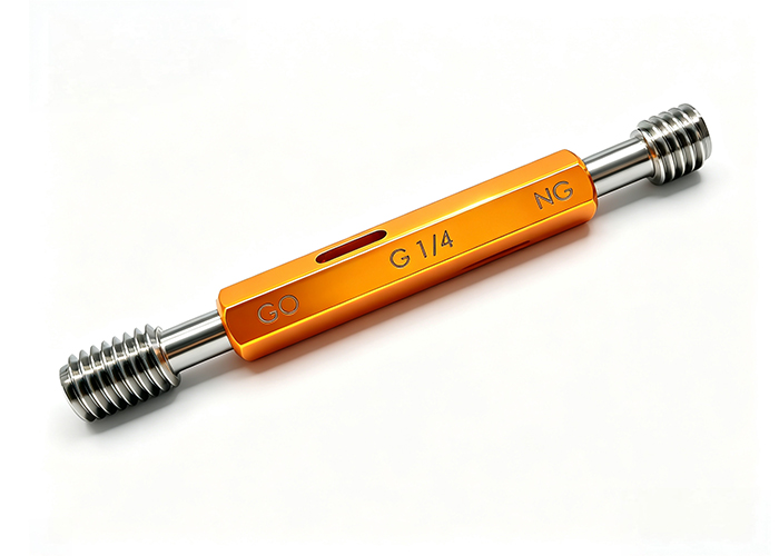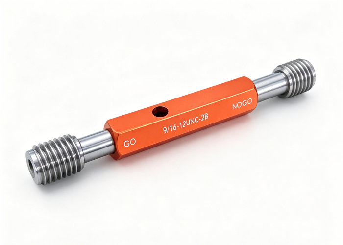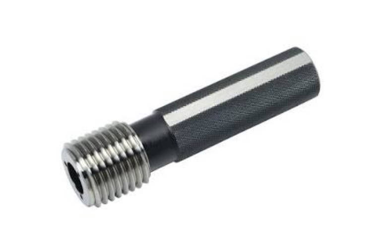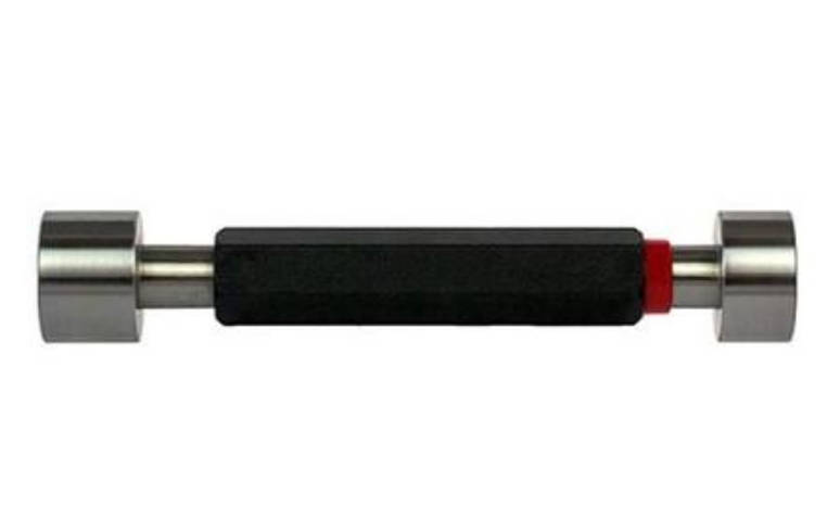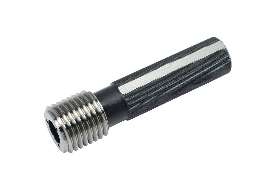
The fundamental difference between a thread plug gauge and a thread ring gauge comes down to the geometry of the workpiece: a thread plug gauge inspects internal threads (such as tapped holes and nuts), while a thread ring gauge inspects external threads (such as bolts, studs, and threaded shafts).
Both tools serve as fixed-limit attribute gauges using a Go/No-Go verification principle to evaluate functional pitch diameter and thread form limits without taking direct dimensional readings. Selecting the correct gauge pair requires matching the component’s internal or external orientation, verifying the applicable thread tolerance class (such as 6H versus 6g in Metric, or 2B versus 2A in Unified standards), and evaluating tool wear against production volume.
This guide details the mechanical differences between these two gauge types, examines how Go and No-Go elements function on the shop floor, clarifies tolerance pairing rules, and provides a structured procurement framework for manufacturing operations.
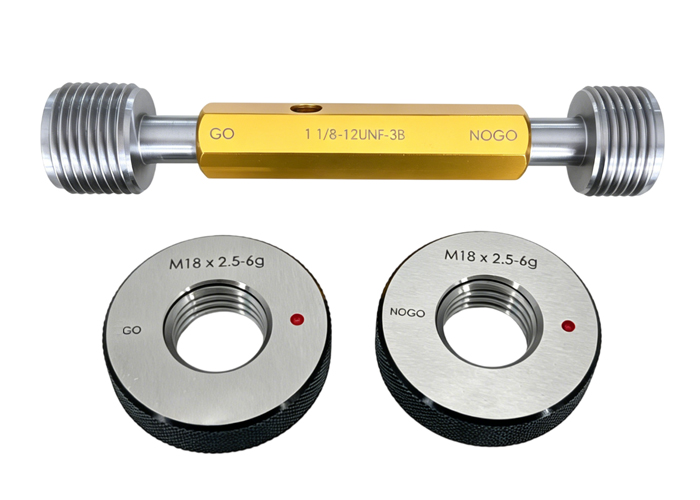
Core Distinction: Internal vs. External Thread Inspection
Thread inspection in precision manufacturing is divided strictly by internal and external workpiece geometry. Thread plug gauges and thread ring gauges cannot be interchanged because each is engineered to assess opposing contact surfaces.
Thread Gauge Functional Assignment
| Inspection Category | Internal Threads | External Threads |
| Target Workpieces | Tapped holes, nuts, threaded bores, hydraulic manifolds | Screws, bolts, threaded studs, shafts, pipe fittings |
| Applicable Gauge | Thread Plug Gauge | Thread Ring Gauge |
| Physical Form Factor | Cylindrical threaded body with hexagonal or taper-lock handle | Annular circular ring encased in a knurled steel sleeve |
| Inspection Focus | Inspects internal pitch diameter limits, flank angles, and lead from inside the hole | Inspects external flank angles, pitch diameter limits, and major/minor boundaries over the shaft |
Thread Plug Gauges (Internal Inspection): These gauges feature externally threaded cylindrical members mounted onto a central hexagonal or taper-lock handle. The inspector threads the gauge into an internally tapped hole or threaded bore to verify that internal pitch diameter, flank angle, and lead fall within specified minimum and maximum material boundaries.
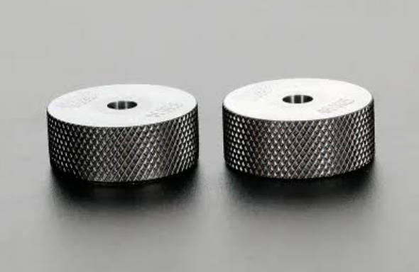
Thread Ring Gauges (External Inspection): These gauges are circular rings with internally ground threads encased in knurled steel bodies. The operator threads the ring over a machined external thread to ensure the outside profile mates correctly without binding or excessive looseness.
Using the wrong gauge type is mechanically impossible; an external thread cannot accept a plug, nor can a ring gauge evaluate an internal thread. Quality control setups pair both gauge styles whenever an assembly requires matching male and female threaded parts.
Direct Comparison: Thread Plug Gauges vs. Thread Ring Gauges
While both tools verify thread integrity, their structural designs, critical wear locations, and operational handling differ across workshop environments.
| Engineering Factor | Thread Plug Gauge | Thread Ring Gauge |
| Target Workpiece | Internal threads (nuts, drilled/tapped blocks, threaded valve ports) | External threads (screws, bolts, turned shafts, threaded fittings) |
| Physical Configuration | Double-ended handle with Go and No-Go threaded members | Separate circular rings (typically supplied as matched Go/No-Go pairs) |
| Primary Wear Surfaces | Crests and flanks of external gauge teeth entering the hole | Roots and flanks of internal gauge teeth sliding over the shaft |
| Handling Method | Held by an anodized aluminum or steel handle; turned by hand | Outer knurled surface gripped directly by fingers |
| Adjustment Capability | Solid, non-adjustable fixed members | Available as solid rings or adjustable split-ring styles calibrated with setting plugs |
| Typical Tolerance Targets | Internal classes: Metric 6H, 5H, 7H; Unified 2B, 3B | External classes: Metric 6g, 4h, 6e; Unified 2A, 3A |
A noticeable visual difference lies in the No-Go member. On a thread plug gauge, the No-Go member has a visibly shorter threaded length and often features an identification groove painted red on the handle. On a thread ring gauge, the No-Go ring is thinner than the Go ring and features an annular groove turned into its outer knurled circumference for immediate tactile identification.
How the Go / No-Go Verification Principle Works for Both Gauges
Thread limit gauges do not generate a variable numerical measurement; instead, they provide an attribute pass/fail result based on Maximum Material Condition (MMC) and Least Material Condition (LMC).
Go / No-Go Decision Logic
| Gauge Type | Go Member Function (Checks MMC) | No-Go Member Function (Checks LMC) | Acceptance Rule |
| Thread Plug Gauge | Must screw smoothly into the tapped hole across the full engagement depth by hand. | Must not enter the hole freely; must stop within 2 to 3 complete turns. | Pass: Full entry on Go, halt on No-Go. Fail: Binds on Go (undersized/tight) or passes on No-Go (oversized). |
| Thread Ring Gauge | Must rotate smoothly down the entire functional length of the male thread using light finger force. | Must not advance down the shaft; must stop within 2 to 3 complete turns. | Pass: Full travel on Go, halt on No-Go. Fail: Jams on Go (oversized/tight) or passes on No-Go (undersized). |
Verification with Thread Plug Gauges
The Go Plug (Checks MMC): Represents the minimum allowable internal pitch diameter and maximum material limit. It must screw smoothly into the tapped hole by hand across the entire engagement length without binding. If it stops prematurely, the hole is undersized, the pitch is incorrect, or chips remain lodged in the thread roots.
The No-Go Plug (Checks LMC): Represents the maximum allowable internal pitch diameter. It must not enter the hole freely. According to standard industrial inspection rules, it should not engage beyond two or three complete turns. If the No-Go plug threads past this threshold, the tapped hole is oversized or stripped, resulting in part rejection.
Verification with Thread Ring Gauges
The Go Ring (Checks MMC): Represents the maximum allowable external pitch diameter and major diameter limit. It must rotate smoothly down the entire functional length of the male thread using light finger force. If it jams, the external thread is oversized, tapered, or exhibits lead error.
The No-Go Ring (Checks LMC): Represents the minimum allowable pitch diameter for the external profile. It must not slip down the shaft; engagement must halt within two to three turns. Full engagement indicates that excessive material was removed during machining, which compromises tensile joint strength.
Matching Thread Standards & Tolerance Classes (ISO vs. UN/UNJ)
A common mistake in tooling procurement is specifying a thread diameter and pitch without designating matching tolerance classes. Internal and external threads follow distinct standardized lettering systems.
Uppercase Letters Indicate Internal Threads (Plug Gauges):
Metric (ISO): Common classes include 6H (standard commercial tolerance), 5H (tighter fit for precision assemblies), and 7H (looser fit for coatings).
Unified (UN/UNC/UNF): Designated as Class 2B (standard production), Class 3B (tight aerospace/instrument fit), or Class 1B (loose utility fit).
Lowercase Letters Indicate External Threads (Ring Gauges):
Metric (ISO): Standard classes include 6g (standard allowance for clearance/plating) and 4h/6h (zero-allowance precision fits).
Unified (UN/UNC/UNF): Designated as Class 2A (standard with clearance), Class 3A (close tolerance without clearance), or Class 1A.
Standard Mating Tolerance Pairs
| Standard Type | Internal Tolerance (Plug Gauge) | External Tolerance (Ring Gauge) | Application Context |
| Metric Standard | 6H | 6g | General commercial machining, standard fasteners |
| Metric Precision Fit | 5H | 4h / 6h | Tight alignment pins, high-precision instrumentation |
| Unified Standard | Class 2B | Class 2A | Standard bolts, nuts, and industrial machinery |
| Unified Precision | Class 3B | Class 3A | Aerospace, defense, and zero-backlash assemblies |
When parts require surface treatments (such as zinc plating, anodizing, or phosphate coatings), machining engineers must inspect threads using pre-plate gauges. Pre-plate plug gauges are manufactured slightly undersized, and pre-plate ring gauges are made slightly oversized to accommodate coating thickness without causing mechanical interference during final assembly.
Material Selection & Wear Considerations: Tool Steel vs. Tungsten Carbide
Because thread gauges rely on physical contact, frictional sliding causes continuous surface wear. Selecting the proper gauge substrate depends on production volume, part abrasiveness, and replacement budgets.
1. Hardened Tool Steel (e.g., GCr15 / O1 / A2)
Application Suitability: Ideal for low-to-medium production runs, toolroom verification, and standard machine-side spot-checks.
Characteristics: Offers high core toughness and cost-effective initial procurement.
Wear Factor: Steel gauges wear faster when used to check abrasive materials like cast iron, stainless steel, or unlubricated aluminum. They require frequent recalibration to catch dimensional drift.
2. Tungsten Carbide
Application Suitability: Well-suited for high-volume automated manufacturing lines, high-frequency manual inspection, and abrasive non-ferrous components.
Characteristics: Exceptional surface hardness and wear resistance, maintaining critical pitch diameter up to 10 to 20 times longer than hardened tool steel under comparable conditions.
Wear Factor: Carbide is more brittle than tool steel; dropping a carbide plug gauge on a concrete floor can chip or fracture the ground threads.
For high-speed production environments, quality managers often balance costs by deploying carbide Go members (which absorb 90% of active sliding contact) paired with hardened tool steel No-Go members (which contact only rejected parts).
Industrial Applications: Where Are Both Gauges Used Simultaneously?
Comprehensive quality management requires running thread plug and ring gauges together across downstream manufacturing cells to guarantee complete mechanical interchangeability.
Parallel Gauge Usage in Industrial Assemblies
| Industry / Application | Internal Inspection Focus (Plug Gauge) | External Inspection Focus (Ring Gauge) | Operational Objective |
| Hydraulic & Pneumatic Manifolds | Tapped NPT, BSPP, or metric O-ring fluid ports | Steel pipe nipples, hose barbs, and compression fittings | Ensure pressure-tight seal and prevent oil leakage under operating pressure |
| Industrial Processing Machinery | Internal tapped platen holes and mounting plates on an extrusion line | High-tensile tie-rods, barrel tie-bars, and heated die studs | Prevent thread galling during high-torque machine assembly |
| Automotive Powertrain | Tapped holes in engine cylinder blocks and transmission casings | Turned engine studs, suspension bolts, and wheel lugs | Guarantee precise torque retention and prevent stripped threads during automated assembly |
Hydraulic and Pneumatic Manifolds: Hydraulic valve blocks feature internal ports verified by thread plug gauges. The steel fittings and connectors that thread into these blocks are checked on external turning centers using thread ring gauges. A dimensional mismatch on either side causes fluid leakage under system operating pressures.
Machinery Assembly & Heavy Equipment: Heavy processing equipment—such as feed screws, barrel tie-bars, and heated die heads used on an extrusion line—relies on high-tensile threaded tie-rods and bolted structural flanges. Internal tapped holes in the heavy platens require plug gauge verification, while structural studs demand ring gauge inspection to prevent thread galling during high-torque assembly.
Automotive Fasteners and Powertrain Mounts: High-volume bolt manufacturers turn out thousands of external engine studs per hour, relying on thread ring gauges for stage-gate QC. Simultaneously, engine block engine-mount holes undergo plug gauge testing to prevent stripped threads during automated assembly.
Procurement Checklist: What to Specify Before Ordering from Mihe
When ordering standard or custom thread inspection tooling from a manufacturer like Mihe, providing incomplete parameters delays manufacturing and calibration. Use this technical checklist to finalize your order details:
Thread Nominal Size and Pitch: Specify standard metric diameter and pitch (e.g., M12 x 1.75) or Unified nominal size and TPI (e.g., 1/2-13 UNC, 3/8-24 UNF).
Gauge Style: Clarify whether the application requires a Thread Plug Gauge (Double-ended Go/No-Go with handle) or a Thread Ring Gauge (Individual Go ring, individual No-Go ring, or a matched pair).
Tolerance Class: Clearly designate internal classes (e.g., 6H, 2B, 3B) for plug gauges or external classes (e.g., 6g, 2A, 3A) for ring gauges.
Pre-Plate or After-Plate Requirement: Confirm whether the stated dimensions apply to bare metal before coating or to the final coated thread.
Material Grade: Specify standard hardened alloy tool steel or wear-resistant tungsten carbide based on anticipated inspection cycles.
Direction of Thread: Default threads are Right-Hand (RH). If left-hand threads are needed, explicitly state “LH” to avoid machining errors.
Calibration Documentation: Confirm whether an ISO/IEC 17025 accredited calibration certificate with traceable pitch diameter inspection records is required for your plant’s quality records.
Key Takeaways
Opposing Inspection Roles: Thread plug gauges verify internal threads (tapped holes, nuts); thread ring gauges verify external threads (screws, studs, threaded shafts).
Dual Go/No-Go Verification: The Go member checks the Maximum Material Condition across the full thread length, while the No-Go member verifies the Least Material Condition and must not advance beyond two to three turns.
Tolerance Class Matching: Internal threads use uppercase tolerance notations (e.g., 6H, 2B), whereas external threads use lowercase notations (e.g., 6g, 2A).
Substrate Strategy: Use hardened tool steel for lower production volumes; implement tungsten carbide for Go elements on high-volume production lines to reduce wear.
Calibration Setting: Thread ring gauges cannot be verified using a regular thread plug gauge; they require a specialized truncated setting plug gauge for calibration.
Frequently Asked Questions (FAQ)
Can a thread plug gauge and a thread ring gauge check each other directly?
No. Standard working thread plug gauges and working thread ring gauges cannot verify one another. A standard plug gauge is designed to check the pitch diameter limits of an internally tapped part, not a ring gauge. To calibrate or adjust a thread ring gauge, technicians use a dedicated Master Setting Plug Gauge, which has truncated thread profiles manufactured to specialized calibration tolerances.
How often should thread plug and ring gauges be recalibrated?
Recalibration intervals depend on usage frequency, workpiece abrasiveness, and internal quality procedures. As a general shop-floor standard, active working gauges in daily production are checked every 6 to 12 months. Facilities processing abrasive materials like stainless steel or unlubricated cast iron may require monthly calibration or cycle-count tracking (e.g., recalibrating after every 2,500 to 5,000 part checks).
What causes a thread ring gauge to wear out faster than a plug gauge?
External threads processed by turning, rolling, or milling often collect cutting oil, metal swarf, and fine burrs. When an operator threads a ring gauge over an uncleaned part, these chips act as an abrasive paste against the internal gauge teeth. Thread plug gauges, while also susceptible to chips inside blind holes, generally encounter fewer loose burrs if tapped holes are blown clear with compressed air prior to testing.
Do thread limit gauges measure exact pitch diameter dimensions?
No. Thread plug and ring gauges are attribute inspection tools, not variable measuring instruments. They determine whether a thread falls inside allowable engineering tolerance boundaries (pass or fail). To obtain numerical pitch diameter data for statistical process control (SPC), machine operators must use three-wire systems, optical comparators, or thread measuring micrometers.