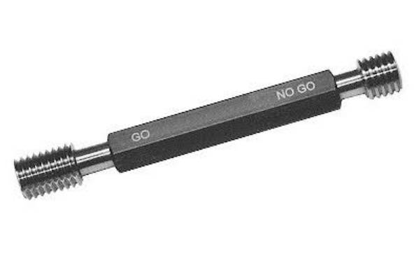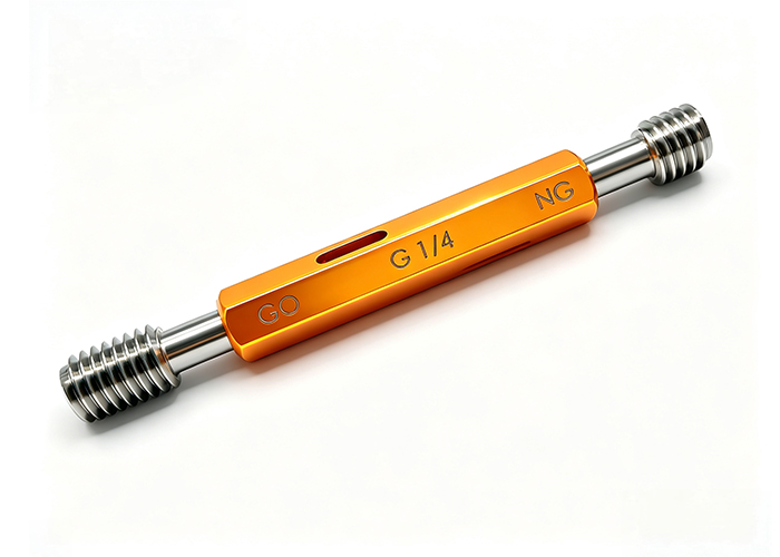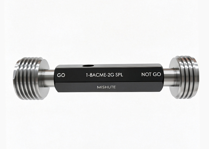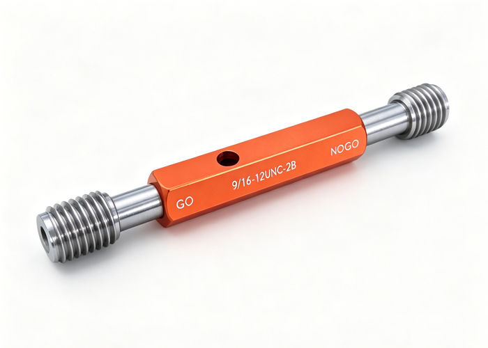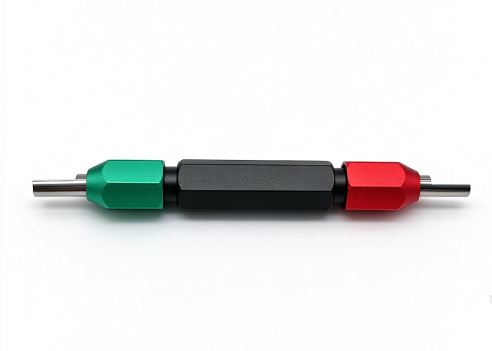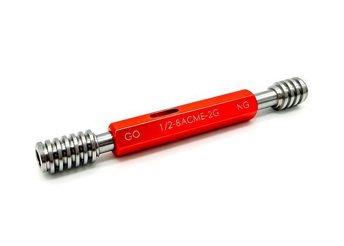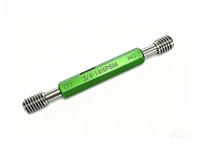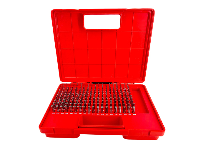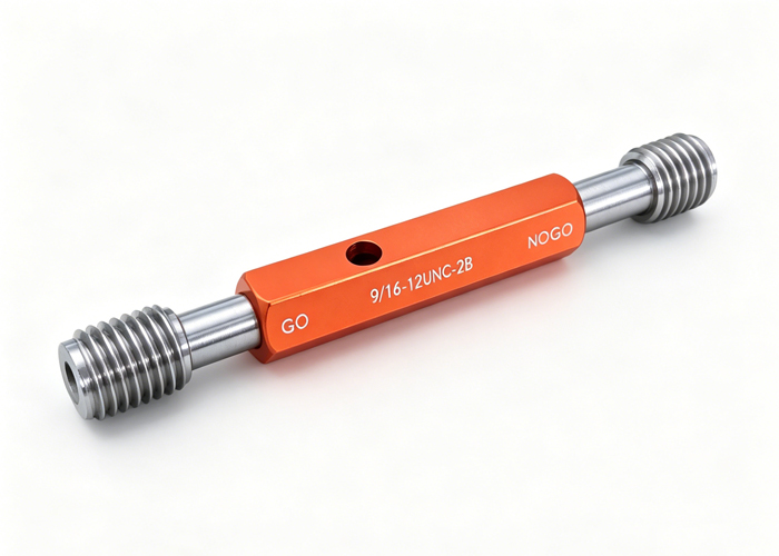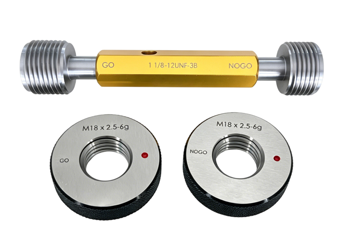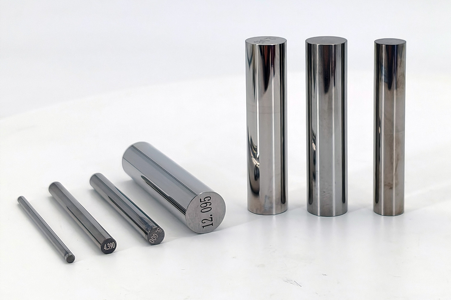
Aerospace fastener inspection requires precision far beyond standard commercial hardware because flight-critical joints operate under severe cyclical stress, vibration, and thermal extremes. Meeting quality standards like AS9100 and MIL-SPEC depends directly on using specialized aerospace thread gauges engineered specifically for controlled-root geometries such as UNJ profiles. Substituting standard unified thread tools compromises pitch diameter verification, risks premature thread stripping, and creates audit failures during quality compliance reviews.
This guide outlines the critical geometric differences between UN and UNJ thread forms, details MIL-SPEC gaging classifications (System 21, 22, and 23), establishes metrology traceability requirements for AS9100 audits, and provides a clear procurement framework for selecting wear-resistant inspection tooling for high-nickel and titanium alloys.

Why Aerospace Fastener Thread Inspection Demands Beyond-Standard Precision
Fasteners used in airframes, propulsion assemblies, and landing gear must resist fatigue failure caused by sustained cyclic loading. A microscopic defect in pitch diameter, lead error, or flank angle can concentrate stress within the root radius, initiating microfractures that lead to structural failure.
Standard commercial fasteners rely on basic Go and No-Go checks to confirm that components assemble smoothly. In contrast, aerospace thread inspection verifies both dimensional assembly and structural integrity under load. Aerospace quality control requires:
Strict compliance with controlled-radius tooth profiles to prevent notch fatigue.
Continuous verification of dimensional limits before and after protective plating or dry-film lubricants are applied.
Unbroken calibration traceability back to national standards to satisfy aerospace audit trails.
Using standard industrial tooling on aircraft-grade fasteners can yield false acceptance readings. Specialized precision thread gauges ground to exact aerospace limits prevent defective components from entering the flight assembly inventory.
UNJ vs. UN Threads: Critical Root Radius and Gauge Engagement Differences
The primary geometric difference between standard Unified Inch (UN) threads and aerospace Unified Miniature/Inch (UNJ) threads lies in the root radius of the external thread. Defined by standards like ASME B1.15 and military specification MIL-S-8879, UNJ threads feature an enlarged, smoothly blended root radius ranging from $0.15011P$ to $0.18042P$ (where $P$ is the thread pitch). This modification eliminates sharp internal corners, significantly improving fatigue life.
Because the external thread root is enlarged, the minor diameter of the mating internal thread must be increased to prevent mechanical interference. Consequently, standard UN gauges cannot accurately inspect UNJ fastener threads.
| Geometric & Inspection Parameter | Standard UN / UNR Profile (ASME B1.1) | Aerospace UNJ Profile (ASME B1.15 / MIL-S-8879) | Impact on Gaging & Tooling Selection |
| External Root Contour | Flat or casually rounded (UNR min $0.108P$) | Continuous controlled radius ($0.15011P$ to $0.18042P$) | Standard UN ring gauges will interfere with the enlarged UNJ root radius, resulting in false rejects. |
| Internal Minor Diameter | Standard clearance cut | Truncated/enlarged to clear the external root radius | Standard UN plug gauges may pass an internal thread whose minor diameter is cut too small. |
| Thread Ring Gauge Crest | Standard truncation | Cleared/truncated crest to clear root radius | UNJ external threads require dedicated UNJ thread gauges ground with root relief. |
| Fit Classifications | Typically Class 2A / 2B or 3A / 3B | Primarily Class 3A / 3B (tightest standard tolerances) | Narrow pitch diameter tolerance bands demand Class X or Class W gauge manufacturing accuracy. |
| Tool Interchangeability | Interchangeable across general mechanical hardware | Non-interchangeable; mandatory separation in tool cribs | Mixing UN and UNJ gauges during quality checks leads to immediate flight-hardware rejection. |
When inspecting external UNJ bolts and studs, UNJ thread plug gauges and ring gauges must feature root clearance geometry. Using a standard 3A ring gauge on a 3A UNJ thread causes the gauge crest to bind on the enlarged root radius, falsely indicating that the pitch diameter is oversized.
Navigating MIL-SPEC Requirements: Variable vs. Go/No-Go Gaging (System 21, 22, and 23)
Military and defense specifications—historically anchored by MIL-S-8879 and currently governed under ASME B1.3—categorize dimensional thread inspection into three distinct verification levels. Choosing the correct inspection method depends on whether the fastener is classified as a safety-critical flight component or a non-structural secondary bracket.
| Fastener Criticality & Application | ASME B1.3 Gaging System | Verification Method & Scope | Tooling & Equipment Deployed |
| Non-Critical / Secondary Fasteners (Brackets, access panels, interior cabin hardware) | System 21 | Attribute Verification: Interchangeability check at maximum and minimum material limits (MMC/LMC). | Fixed Limit Tooling: • Go No-Go thread gauges (Thread Rings & Plugs) |
| Critical Structural Fasteners (Airframe joints, engine mounts, wing spars) | System 22 | Functional Size & Pitch Diameter: Dual validation of maximum material size and quantitative pitch diameter. | Combined Verification: • Fixed Go / No-Go tooling • Pitch diameter indicating comparators (Cone & Vee rolls) |
| Safety-Critical / Rotating Hardware (Rotor-head bolts, turbine shafts, high-vibration joints) | System 23 | Full Independent Parameter Verification: Discrete validation of lead, flank angle, taper, roundness, and root blend. | Variable Dimensional Tooling: • Multi-rib & single-rib indicating gauges • Optical / contact profilometers • Form & lead analyzing instruments |
System 21: Attribute Verification
System 21 provides a baseline check for interchangeable assembly. It uses fixed-limit Go No-Go thread gauges to verify that the fastener does not exceed maximum material condition (MMC) or fall below least material condition (LMC). While simple and fast for high-volume sorting, System 21 does not provide quantitative data on actual pitch diameter, taper, or lead error.
System 22: Functional Size and Pitch Diameter Control
Most structural aerospace fasteners require System 22 inspection. This method pairs functional limit checks with variable measurement tools (such as indicating thread comparators using cone-and-vee or multi-rib rolls). It independently validates the actual pitch diameter alongside functional size, catching cumulative manufacturing errors before the fastener is installed.
System 23: Complete Dimensional Evaluation
Reserved for critical components such as rotor-head bolts, turbine shaft threads, and fracture-critical tension links, System 23 requires independent evaluation of each thread characteristic:
Pitch diameter across the entire engagement length.
Flank angle deviations.
Lead and helical path variations.
Taper, out-of-roundness, and thread root blend consistency.
While fixed-limit gauges serve as the frontline defense in System 21 and 22 production lines, they must be paired with variable measuring systems when comprehensive MIL-SPEC compliance data is mandated.
Meeting AS9100 Metrology Requirements: Calibration, Traceability, and Gauge Life Management
Under AS9100 Clause 7.1.5 (Monitoring and Measuring Resources), aerospace manufacturers and suppliers must prove that every inspection device is calibrated, documented, and traceable to national or international standards (such as NIST). Because thread ring gauges and plug gauges experience continuous friction during use, maintaining strict calibration control is vital for audit compliance.
1. Temperature-Controlled Calibration Environment
Thread tolerances for Class 3A and 3B aerospace fits are exceptionally tight. Calibration must occur in an environmentally controlled metrology room maintained at the standard reference temperature of 20°C (68°F). Sufficient thermal soak time is necessary before measuring to eliminate errors from thermal expansion between master setting plugs and working gauges.
2. Truncated Setting Plugs for Thread Rings
Adjustable and solid thread ring gauges cannot be verified using standard optical or internal micrometers alone. Quality teams must verify ring gauges using truncated setting plug gauges. A truncated setting plug features two distinct axial sections:
A full-form section that checks functional fit, flank angle, and clearance.
A truncated section that isolates and measures pitch diameter wear.
When conducting regular inspections, verifying ring gauges against both sections ensures that pitch diameter expansion and crest wear are caught before the tool produces out-of-tolerance parts.
3. Traceability Documentation Requirements
During an AS9100 audit, measuring instruments without traceable documentation are treated as non-conforming items. Every working gauge on the shop floor must link directly to a valid calibration certificate that includes:
Unique gauge serial number and exact pitch/thread identification.
Actual measured pitch diameter (not just a generic “pass” notation).
Stated measurement uncertainty.
Explicit calibration standard reference (such as ISO/IEC 17025 accredited laboratory approval).
Defined calibration interval and next due date, calculated using tool usage frequency and material abrasiveness.
Tool Steels, Carbides, and Surface Treatments: Selecting Gauges for Exotic Alloys
Aerospace fasteners are rarely machined from free-cutting steels. They are predominantly turned, ground, or rolled from work-hardening superalloys, including Ti-6Al-4V (Grade 5 Titanium), Inconel 718, A286, and 17-4PH stainless steel. These alloys generate severe friction, galling, and abrasive wear, which can quickly degrade conventional tool steel gauges.
| Gauge Material / Treatment | Hardness Range | Galling & Wear Resistance | Recommended Workpiece Materials | Tool Life & Economic Evaluation |
| Standard Hardened Tool Steel (O1 / W1 / L6) | 60–62 HRC | Low to Moderate; susceptible to micro-galling | Aluminum structural fittings, brass, mild carbon alloys | Lowest initial cost; rapidly wears out of tolerance on nickel/titanium alloys. |
| High-Carbon Tool Steel (D2 / High-Speed Steel) | 62–64 HRC | Moderate; adequate abrasion resistance | General 300/400-series stainless, low-volume A286 bolts | Moderate cost; reliable for low-to-medium runs with adequate lubrication. |
| Hard Chrome Plated Steel (0.0001″–0.0002″ per flank) | ~68–72 HRC equiv. | High; slick surface resists material pick-up | High-strength stainless steels (17-4PH, 15-5PH, A286) | Cost-effective for extended production; base steel wears quickly once chrome layer chips. |
| Solid Tungsten Carbide | 88–92 HRA | Extreme; exceptional flank abrasion resistance | Titanium (Ti-6Al-4V), Inconel 718, Waspaloy, Hastelloy | Higher upfront tooling cost; yields 10–20× longer service life in abrasive and dry setups. |
Selecting appropriate gauge materials balances purchase price against working service life:
Hardened Tool Steel (D2 / O1)
Standard tool steels heat-treated to 60–62 HRC provide an economical option for short production runs or secondary aluminum components. However, when inspecting dry, unlubricated titanium or nickel-alloy threads, standard tool steel gauges can gall and wear past allowable limits within a few hundred cycles.
Hard Chrome Plating
Applying thin, dense industrial chrome plating (0.0001″ to 0.0002″ per side) onto tool steel gauge flanks significantly reduces surface friction. Chrome-plated gauges resist galling when checking stainless steels and soft structural alloys, extending calibration stability across extended production runs.
Solid Tungsten Carbide
For high-volume fastener manufacturing or automated inspection lines, carbide thread plug gauges provide superior wear resistance. Tungsten carbide offers extreme hardness and resistance to flank abrasion. While the initial investment is higher, carbide gauges often provide 10 to 20 times the working lifespan of tool steel when checking Inconel and titanium fasteners, reducing recalibration frequency and tool crib downtime.
Procurement Checklist: Ordering Custom and Standard Aerospace Thread Gauges
Procurement delays and engineering disputes often stem from incomplete specification details provided during initial quoting. When sourcing custom aerospace thread gauges or standard production sets, provide your gauge manufacturer with a complete technical definition:
Exact Thread Designation & Standard: Specify the complete designation, including thread series and nominal size (e.g., 0.2500-28 UNJF – 3A per ASME B1.15). Never truncate the “J” designation.
Tolerance Class & Direction: State whether the inspection is for internal threads (e.g., 3B for locknuts and tapped airframe bosses) or external threads (e.g., 3A for engine bolts and studs).
Coating Condition (Pre-Plate vs. After-Plate): Confirm whether the gauge must measure dimensions before surface treatment or after final plating. If checking threads prior to cadmium, zinc-nickel, or dry-film lubricant application, specify the exact pre-plate pitch diameter limits or the intended coating thickness allowance.
Gauge Accuracy Classification: Specify the required manufacturing tolerance for the gauge itself. Class X is standard for most aerospace inspection environments, while Class W is recommended for master setting plugs and tight-tolerance flight joints.
Gauge Construction Material: Request hardened tool steel, hard chrome-plated steel, or solid tungsten carbide based on workpiece material and production volume.
Certification & Calibration Requirements: Require an ISO/IEC 17025 accredited calibration certificate showing actual pitch diameter, major/minor diameter, lead, and half-angle dimensions traceable to national standards.
Key Takeaways
Geometry Dictates Tooling: Aerospace UNJ threads use an enlarged, controlled root radius ($0.15011P$ to $0.18042P$) that requires dedicated root-cleared ring gauges and modified minor-diameter plug gauges. Standard UN gauges cannot be used.
Fit Class Dictates Gaging Level: High-criticality flight hardware requires System 22 or System 23 verification combining fixed-limit Go/No-Go gauges with pitch diameter comparators to evaluate individual thread characteristics.
Audit-Proof Metrology: AS9100 compliance requires calibrated master setting plugs, controlled 20°C inspection environments, explicit wear limits, and calibration documentation traceable to national standards.
Match Tool Material to Fastener Alloy: Abrasive and work-hardening materials like Inconel 718 and Titanium Ti-6Al-4V quickly wear standard tool steels; using tungsten carbide or chrome-plated gauges prevents premature wear and false rejections.
Clarify Coating Allowances: Always specify whether gauges are intended for pre-plate or after-plate inspection to account for protective finishes.
Frequently Asked Questions (FAQ)
Can a standard UN/UNC/UNF plug gauge be used to check an internal UNJ thread?
No. While internal UNJ threads (UNJC, UNJF, UNJEF) do not have a controlled root radius like external UNJ bolts, their minor diameter is enlarged to provide clearance for the external bolt’s root radius. A standard UN plug gauge has a smaller minor diameter threshold, meaning it could accept a tapped hole whose minor diameter is cut too small, leading to mechanical interference when the UNJ flight bolt is installed.
How often should aerospace thread ring gauges be recalibrated under AS9100?
AS9100 does not set a single, fixed calibration interval for all tools. Instead, recalibration frequency must be determined based on usage rate, workpiece material hardness, part cleanliness, and observed wear trends. In high-volume production lines machining abrasive alloys like titanium, ring gauges may require recalibration monthly or every few hundred cycles, whereas low-volume tooling can follow longer, documented intervals backed by control chart data.
What is the practical difference between Class X and Class W gauge manufacturing tolerances?
Class X and Class W refer to the manufacturing tolerances of the gauges themselves, as defined in ASME B1.2. Class X gauges provide the standard high-precision tolerance used for production inspection of Class 3A and 3B aerospace threads. Class W represents the tightest commercial tolerance available; it is reserved for master setting plugs, critical reference standards, and high-precision aerospace fittings where gauge error must be minimized.
What documents must accompany aerospace thread gauges during an audit?
Auditors typically look for an individual calibration certificate traceable to NIST or an equivalent national metrology institute, issued by an ISO/IEC 17025 accredited laboratory. The certificate must state the serial number, nominal specifications, environmental test conditions (20°C reference), actual measured values for pitch diameter and form, measurement uncertainty, and calibration date.