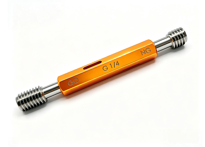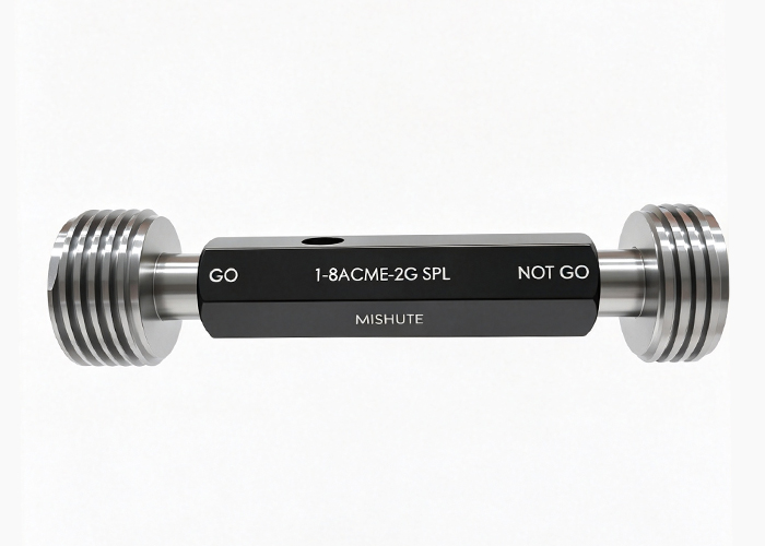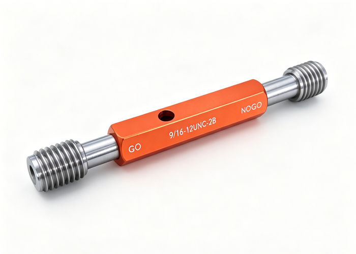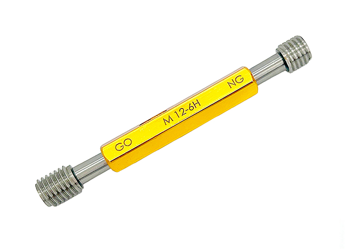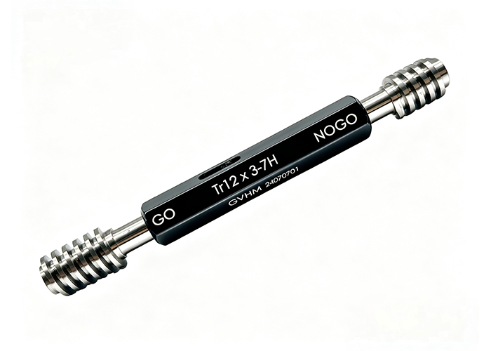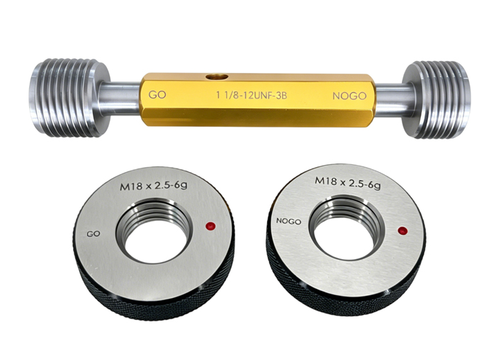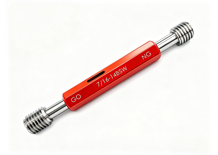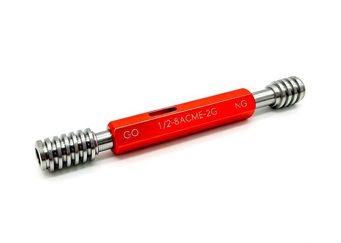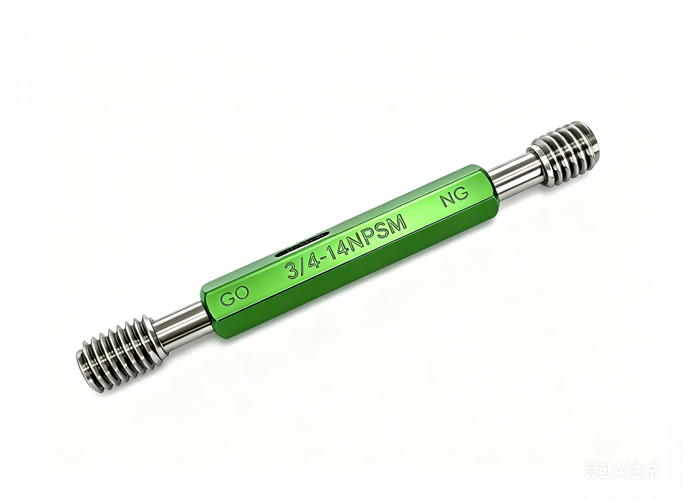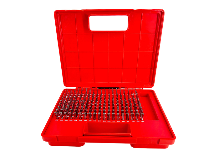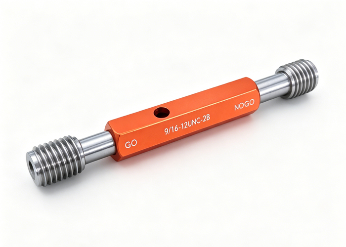
In automated automotive and electric vehicle (EV) production, ensuring 100% thread integrity across high-speed assembly lines requires transitioning from manual spot checks to automated in-line thread verification. Integrating thread gauges directly into automated robotic cells guarantees that tapped holes meet dimensional specifications, prevents cross-threading during automatic fastener driving, and catches structural defects before critical joints are torqued.
Successful implementation depends on balancing rapid cycle times with gauge wear resistance, establishing precise torque-angle thresholds, and integrating compliant tooling to protect both the component and the measuring instrument. This technical guide outlines how engineering and quality teams evaluate, configure, and maintain automated in-line thread inspection to eliminate joint failures on modern production floors.

1. The Zero-Defect Mandate in EV Threaded Assemblies
Electric vehicle architectures place unprecedented mechanical and electrical demands on threaded connections. Large battery enclosures, structural die-cast subframes, and integrated electric drive units rely heavily on internal threads machined directly into lightweight cast aluminum alloys. Unlike non-critical automotive brackets, a compromised thread in an EV chassis can compromise battery hermetic sealing, cause structural fatigue under road vibrations, or interrupt high-voltage grounding paths.
Relying on manual post-process inspection creates unacceptable production bottlenecks and liability risks. If an automated nutrunner encounters a damaged, undersized, or shallow thread downstream, the high-speed driver will stall, gall, or strip the mating threads. In structural aluminum parts, thread stripping often forces expensive rework or the outright scrapping of an entire die-cast battery tray.
| Risk Category | Downstream Assembly Impact | In-Line Gauging Prevention |
| Shallow Tapping Depth | Fastener bottoms out prematurely; insufficient clamp load achieved. | Verifies full usable thread depth before fastener presentation. |
| Pitch Diameter Under-Sizing | Immediate bolt galling or drive spindle motor stall under target torque. | Confirms pitch diameter tolerance via controlled mechanical engagement. |
| Cross-Threaded Entry | Stripped internal threads; loss of structural joint integrity. | Detects misaligned lead-in threads prior to structural bolt insertion. |
| Entrapped Chips / Burrs | Erroneous torque readings; joint loosens during vehicle operation. | Flags internal obstruction through torque-depth threshold monitoring. |
Implementing in-line verification verifies every critical internal thread immediately following machining or prior to automated bolt fastening, establishing a closed-loop quality barrier against assembly failures.
2. Manual Inspection vs. In-Line Thread Gauging: Operational Trade-offs
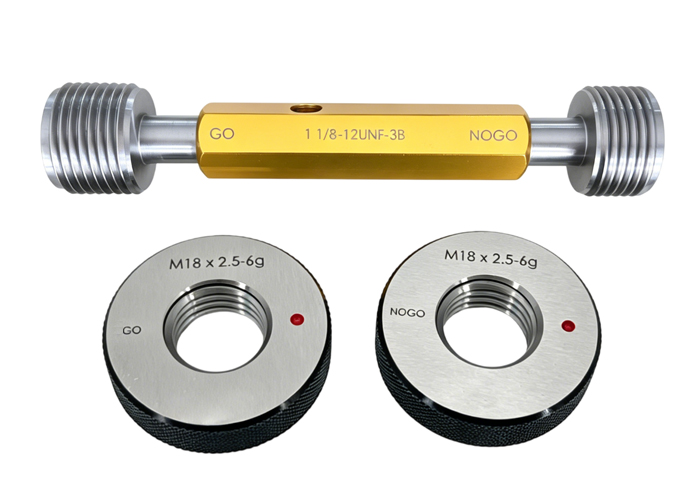
Traditional quality assurance protocols rely on operators using handheld Go and No-Go plug gauges on a statistical sampling schedule. While manual gauging remains practical for small-batch testing, it introduces operational vulnerabilities when scaled across automated assembly lines running cycle times under 30 seconds.
Operators apply variable rotational speed, variable axial pressure, and inconsistent entry angles. Over an eight-hour shift, operator fatigue can lead to forced gauge insertion—yielding false passes on borderline threads—or premature rejection of acceptable holes due to slight angular misalignment. Furthermore, statistical sampling means that hundreds of parts may be processed between inspection intervals before a worn tap or broken drill is discovered.
| Evaluation Parameter | Manual Go / No-Go Gauging | Automated In-Line Thread Gauging |
| Inspection Cycle Time | 15–40 seconds per hole (highly dependent on operator fatigue). | 2–5 seconds per hole (synchronized to automated transfer cycles). |
| Measurement Consistency | Variable; influenced by operator grip, approach angle, and torque. | Repeatable; controlled rotational speed, depth, and torque thresholds. |
| Data Logging & Traceability | Manual logging or periodic batch entry into statistical software. | 100% digital logging tied to vehicle VIN or sub-assembly serial numbers. |
| Tool Wear Predictability | Unmonitored; gauge wear discovered only during routine tool audits. | Predictable; cycle-counter logging with automated wear offset tracking. |
| Galling / Thread Damage Risk | Moderate; operator can cross-thread or force-fit a tight thread. | Low; protected by instant torque shutoff and axial float mechanisms. |
| Defect Containment | Batch quarantine required upon finding a defect during sample runs. | Instant; marks defect and diverts part before value-added assembly steps. |
Automated gauging eliminates human subjectivity, shortens takt times, and captures immediate trend data when taps begin to wear upstream.
3. Core Failure Modes in Automated Thread Gauging & Root-Cause Engineering
Operating thread gauges inside automated cells introduces mechanical dynamics distinct from manual inspection. Without a human operator feeling the initial thread engagement, automated spindles must rely on precision programming and mechanical protection to prevent false rejects and tool breakage.
| Engagement Phase | Monitored Depth Condition | Primary Defect Classification | Mechanical Significance |
| Hole Entry | Depth < 1 Pitch | Misalignment / Lead-in Burr / Cross-Thread | Gauge binds before entering lead helix; radial off-center. |
| Mid-Stroke | Depth < Target Specification | Swarf Compaction / Tap Taper Wear / Plating | Gauge stalls along the bore due to restriction or debris. |
| Bottom Stroke | Depth = Target Specification | Conformance Confirmed (Acceptable Joint) | Pitch diameter and functional depth meet full tolerance. |
Common Root Causes of False Rejections
Angular and Centerline Misalignment
If the robotic actuator or spindle presents the gauge even one degree off the hole’s true mechanical axis, the gauge flank binds against the female thread crest. This friction generates a rapid torque spike that mimics an undersized pitch diameter, triggering a false reject.
Entrapped Swarf and Particulate Contamination
In aluminum and ductile iron machining, stringy swarf or loose chips can remain inside blind tapped holes despite high-pressure washing. As the gauge drives forward, it compresses debris against the bottom of the hole, stopping the gauge before it reaches the programmed verification depth.
Coating and Surface Treatment Variance
Components undergoing e-coating, anodizing, or zinc-flake plating can display irregular coating thicknesses inside threaded bores. If plating tolerances are not accounted for during pre-plate machining, nominal precision thread plug gauges will bind against the restricted pitch diameter.
| Failure Symptom | Mechanical or Tooling Root Cause | Corrective Engineering Action |
| Instant Torque Spike at Hole Entry | Spindle misalignment or severe burr at the first thread crest. | Add compliant radial floating holder; optimize lead-in thread chamfer. |
| Gauge Stalls Mid-Depth | Swarf compaction, taper wear on machining tap, or heavy plating. | Enhance high-pressure chip blow-off cycle; audit upstream tap life. |
| Rapid Gauge Flank Wear | Running high rotational speeds dry or testing abrasive castings. | Apply controlled mist lubrication; evaluate hardened wear-grade alloys. |
| Part Stripping During Back-Off | Reversal speed too high or axial feed out of sync with thread pitch. | Implement electronic pitch-synchronized lead screw drive profiles. |
4. Critical Specifications for Thread Gauges in Automated Stations
Standard hand-use gauges cannot simply be mounted directly into automated spindles. Because automated inspection units cycle thousands of times per week without manual tactile feedback, the geometry, material composition, and surface hardness of the gauge must withstand continuous mechanical cycling.
| Structural Feature | Tooling Section | Engineering Function in Automation |
| Pilot Section | Non-threaded front tip | Cylindrical guide centers tool along bore axis prior to thread contact. |
| Lead-In Section | Initial 1–2 pitch crests | Radiused crest geometry prevents snagging on entrance chamfer edges. |
| Gauging Body | Full thread profile | Calibrated pitch flanks verify functional pitch diameter and form limits. |
| Debris Channel | Longitudinal flutes | Allows chip particles and fluids to escape, preventing hydraulic lock. |
When specifying gauges for automated cells, engineering teams must evaluate several critical mechanical features:
Pilot Guide Steer (Front Guide Point): A non-threaded pilot cylinder ground slightly below the minor diameter helps center the gauge into the hole before thread flank contact, preventing initial cross-threading.
Lead-in Crest Geometry: Modified, radiused lead threads reduce the sharp crest corners found on manual gauges, lowering the risk of snagging on the entry edge of soft aluminum or magnesium castings.
Debris Relief Grooves: Longitudinal flutes cut across the gauge threads provide an exit path for trace chips or residual washing fluid, preventing hydrostatic locking in deep blind holes.
Material and Hardness Selection: Depending on part material, cycle volume, and coating properties, tooling engineers choose between tool steels (such as hardened O1/M2), specialized wear coatings, or solid tungsten carbide inserts. The specific wear treatment and alloy selection should be confirmed with the tool supplier to balance toughness against chipping risks.
| Parameter | Manual Gauge Requirement | In-Line Automated Gauge Requirement | Engineering Impact |
| Pilot Section | Plain chamfer (standard ANSI/ISO). | Cylindrical pilot alignment guide. | Eliminates cross-threading during rapid blind approach. |
| Flank Relief | Standard uninterrupted flanks. | Chip relief flutes optional/recommended. | Prevents hydraulic lock and minor chip jamming. |
| Tool Material | Standard Tool Steel (e.g., ~60–62 HRC). | High-Wear Tool Steels or Carbide Inserts.* | Extends calibration intervals under unlubricated cycles. |
| Tolerance Class | Standard Class 6H / 2B tolerances. | Matched class; accounting for plating margins. | Prevents false rejections on coated fastener assemblies. |
| Shank Interface | Standard knurled handle or tapered shank. | Precision ground cylindrical or quick-change DIN. | Ensures low radial runout when locked in drive chucks. |
*Note: Material selection, carbide grades, and surface coating capabilities should be confirmed against the supplier’s specific manufacturing parameters.
5. Integration Architecture: Aligning Gauges, Floating Holders, and Torque Feedback
Deploying automated thread gauging solutions requires tight integration between three sub-systems: the driving mechanism, compliance tooling, and real-time process monitoring. A rigid spindle driving a rigid gauge into a rigid workpiece will inevitably bind and cause mechanical damage.
| Layer Number | Integration Sub-System | Primary Function | Operational Target |
| Level 1 | Drive Spindle Unit | Controlled rotational torque and pitch-matched feed. | Maintains electronic synchronization to thread pitch. |
| Level 2 | In-Line Sensors | Simultaneous real-time torque and linear depth monitoring. | Captures torque curves against acceptance window. |
| Level 3 | Compliance Tooling | Multi-axis axial and radial floating tool holder. | Absorbs 0.2–1.0 mm radial and 0.5°–1.5° angular offset. |
| Level 4 | Thread Plug Gauge | Engineered Go / No-Go gauging body with pilot guide. | Enters bore without galling or cross-threading. |
| Level 5 | Workpiece Interface | Cast or machined component female internal thread. | Verifies threaded joint integrity before final fastening. |
1. Controlled Rotation and Feed Synchronization
Modern thread inspection units utilize servomotor-driven spindles where rotation speed and axial displacement are electronically coupled to match the specific thread pitch. Maintaining exact pitch synchronization prevents axial loads from dragging the gauge flanks against the internal threads during insertion and retraction.
2. Radial and Angular Float Compensation
Workpieces mounted on indexing dials or presented by transfer conveyors exhibit minor positioning variations. Integrating a multi-axis floating tool holder allows the gauge to float radially (typically 0.2 mm to 1.0 mm) and pivot angularly (typically 0.5° to 1.5°). This compliance enables the gauge to find its own natural center along the tapped hole’s true axis without inducing side friction.
3. Torque-Depth Window Evaluation
The verification unit measures two variables simultaneously: spindle torque (Nm) and insertion depth (mm). The quality system evaluates the cycle against a defined acceptance window:
Go Check: The gauge must drive forward smoothly below the maximum allowable insertion torque until it crosses the minimum full-thread depth threshold.
No-Go Verification: If checking with a No-Go gauge (or using a single-station torque threshold profile), the unit confirms that torque rises sharply within the first 1 to 2 pitches, verifying that the hole is not oversized or stripped.
Dynamic Retraction: Once target depth is achieved without exceeding torque boundaries, the spindle immediately reverses at a programmed acceleration to clear the station within the allotted cycle time.
6. Calibration, Wear Limits, and Traceability under Automotive Standards
Under automotive quality frameworks such as IATF 16949, measurement equipment integrated directly into production cells must adhere to strict calibration, life-cycle monitoring, and traceability protocols. Because automated in-line thread gauges experience significantly more cycles than laboratory tools, calibration cannot follow arbitrary calendar intervals.
Implementing Cycle-Based Wear Tracking
In-line inspection stations should track cycle counts within the cell PLC or Manufacturing Execution System (MES). Quality engineers establish two threshold levels:
Inspection Warning Threshold: Triggers a maintenance alert to perform an in-cell audit using a certified master ring gauge.
Hard Wear Limit: Stops cell operation once the predetermined cycle limit is reached, requiring physical tool inspection or gauge replacement before production can resume.
| Quality Stage | Verification Event | Operational Focus | Action Trigger & Boundary |
| Stage 1: Shift Start | Master Part Verification | In-station calibration check against reference master. | Zero torque drift; depth readout within calibrated limits. |
| Stage 2: Production Run | In-Line Cycle Tracking | Automatic counter tracks total strokes executed by tool. | MES logs continuous stroke count per active spindle. |
| Stage 3: Preventative Alert | Cycle Warning Alarm | Advance notification for maintenance or tooling team. | Warning flag raised at designated cycle threshold. |
| Stage 4: Recalibration | Tool Audit & Gauge Swap | Metrology bench measurement or full gauge replacement. | Gauge retired if pitch diameter falls outside wear limits. |
| Maintenance Level | Frequency / Trigger | Action Taken | Success Criteria |
| Shift Baseline Check | Start of every production shift. | Inspect master reference part or setting ring in-station. | Zero torque drift; depth readout within calibrated limits. |
| Cycle-Based Audit | Defined batch count (e.g., 5,000–20,000 cycles).* | Dimensional audit of gauge pitch diameter using bench micrometers. | Pitch diameter remains within class wear-tolerance boundaries. |
| Flank Visual Inspection | Scheduled weekly preventive maintenance. | Optical check for flank scoring, chipped lead threads, or galling. | No metal pickup or flank chipping observed. |
| Master Recalibration | Defined by plant quality management cycle. | Off-line laboratory calibration against traceable standards. | Full dimensional certification documentation issued. |
*Note: Exact inspection cycle intervals depend on base material abrasiveness, lubrication presence, and process cycle times. Confirm specific wear limits with tooling engineers.
7. Key Takeaways
Zero-Defect Assembly Protection: In-line thread verification catches shallow tapping, swarf compaction, and pitch diameter deviations before automated drivers attempt bolt installation.
Elimination of Human Variance: Automated gauging provides consistent depth-torque measurement, repeatable inspection cycles under 5 seconds, and complete digital traceability per serial number.
Mechanical Compliance is Essential: Rigid spindles require radial and angular floating holders along with piloted gauge tips to prevent cross-threading and false rejections caused by slight positioning offsets.
Cycle-Driven Maintenance: Tool life must be managed by monitoring cycle counts and evaluating torque curves in real-time rather than relying on standard calendar-based calibration.
8. Frequently Asked Questions (FAQ)
Can an in-line thread gauge check usable thread depth and pitch diameter simultaneously?
Yes. By tracking both axial spindle displacement and motor torque curves, an automated inspection unit confirms that the pitch diameter is cleared while verifying that the gauge reaches the exact specified thread depth without jamming.
What causes a thread gauge to jam repeatedly in aluminum engine or battery components?
Jamming is typically caused by three factors: entrapped chips remaining in blind holes, angular misalignment between the drive spindle and the drilled axis, or rapid metal transfer (galling) on unlubricated tool flanks. Installing floating holders and verifying chip evacuation cycles resolves most jamming issues.
How do surface coatings (such as e-coat or zinc flake) affect thread gauge selection?
Protective coatings reduce internal pitch diameter clearance. When parts require post-machining coating, manufacturing teams must use pre-plate thread taps and corresponding oversized thread gauges, or verify threads after coating using gauges manufactured to the final post-plate tolerance class.
How often should automated thread gauges be replaced?
Replacement intervals vary based on workpiece material, whether lubrication mist is applied, and the gauge alloy selected. Tool steel gauges running unlubricated in cast aluminum or iron typically require audit checks every 5,000 to 20,000 cycles, whereas solid carbide or specialized wear-treated tools deliver significantly longer service lives.