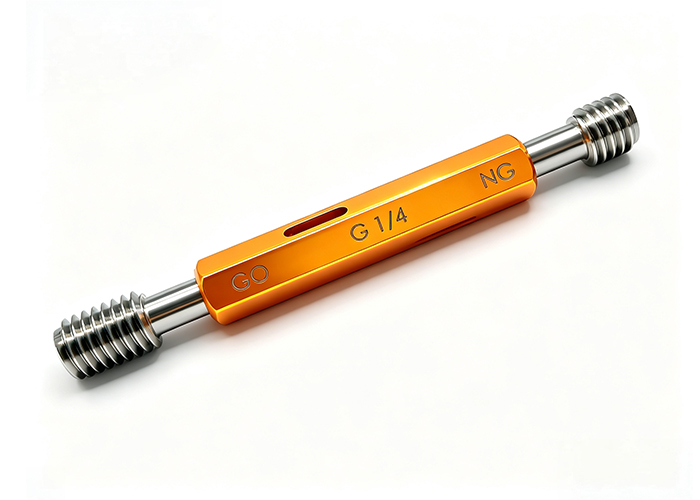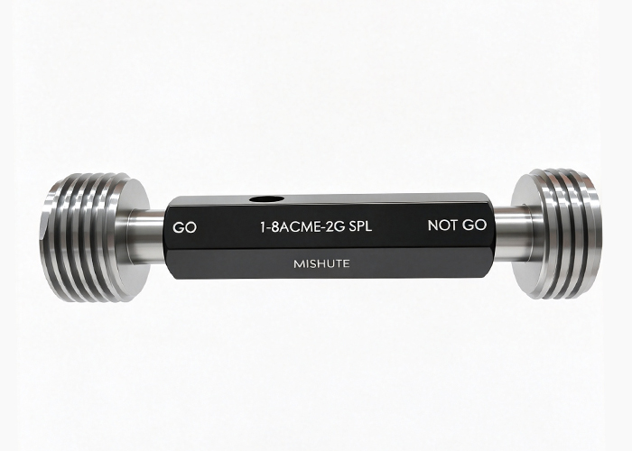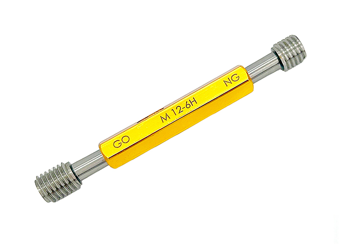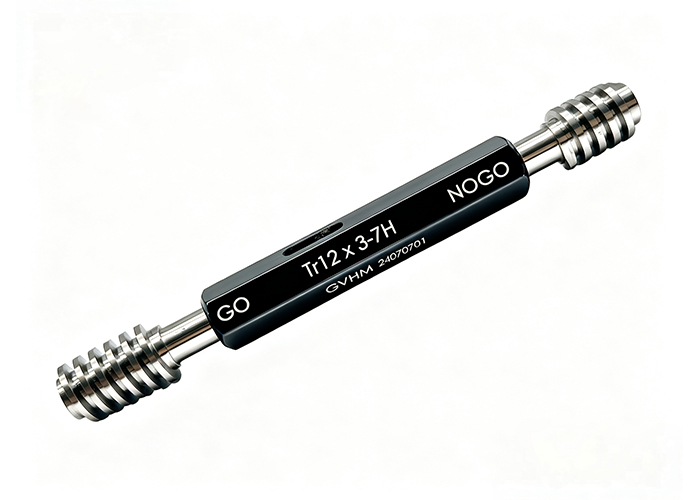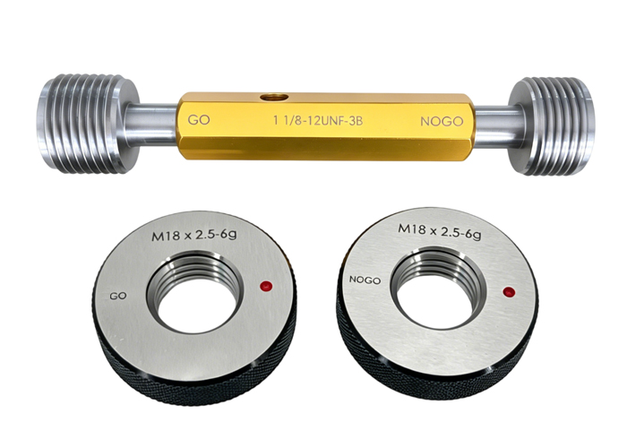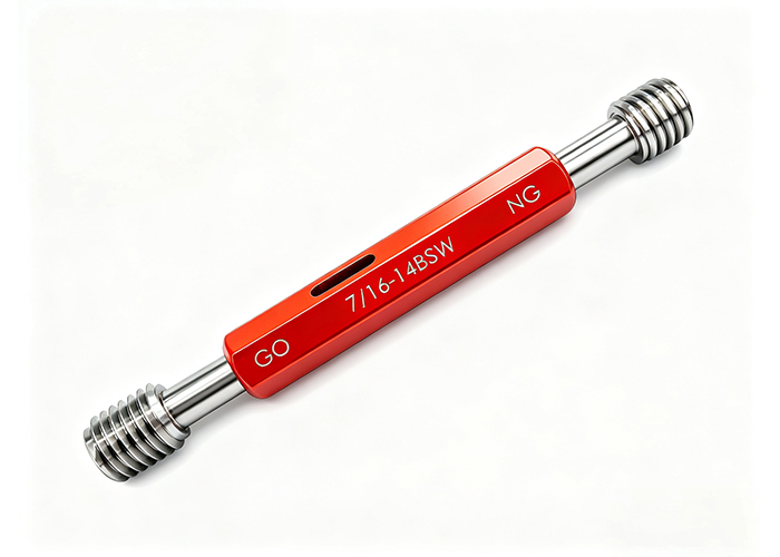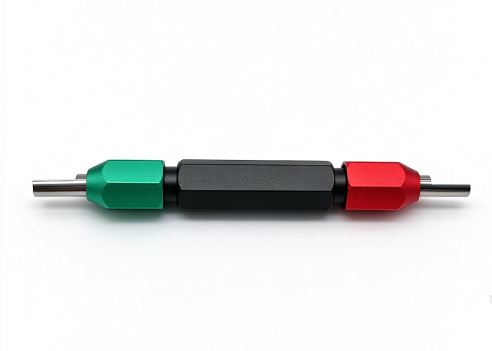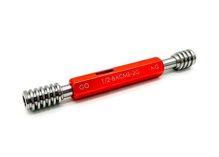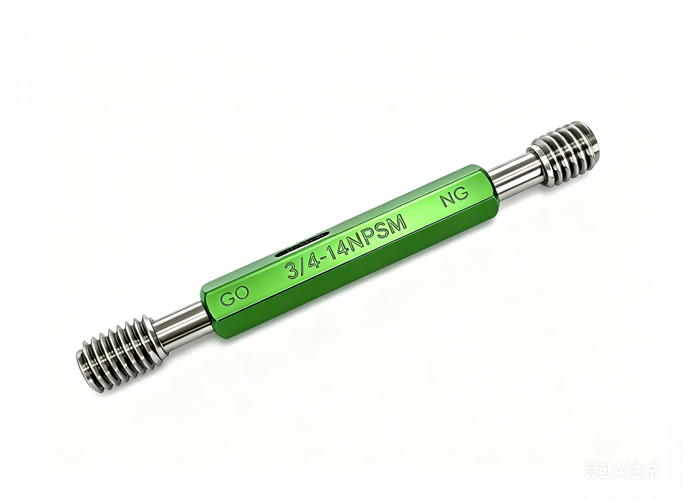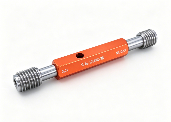
Zero-defect manufacturing in orthopedic implants demands that micro threads on bone screws engage biological tissue or matching fixation plates without micro-motion, galling, or structural fatigue. Achieving this standard requires physical thread gauges capable of verifying functional pitch diameter, flank angle conformance, and lead accuracy at tight manufacturing tolerances. Non-contact optical systems can measure thread profiles and selected geometric parameters, depending on their measurement capabilities and setup. Fixed-limit thread gauges provide a complementary functional acceptance check against specified thread limits. Combining these methods can improve inspection coverage when each method is selected and validated for its intended purpose.
This guide outlines practical methods for deploying Go and No-Go thread gauges in medical manufacturing, managing gauge wear against titanium alloys, qualifying proprietary thread profiles, and establishing repeatable quality assurance protocols.
Precision and Reliability: Thread Inspection Challenges in Bone Screws and Orthopedic Implants
Bone screws, spinal pedicle screws, and cranial fixation pins operate under cyclic dynamic loads within the human body. A dimensional discrepancy in thread geometry can lead to bone strip-out, implant loosening, or localized stress concentrations that induce fastener shearing.
Unlike standard commercial fasteners, orthopedic fasteners present specific metrological hurdles:
Micro-Scale Pitches: Some medical implant designs use fine-pitch or micro-thread geometries that require careful control of thread dimensions and functional engagement. The applicable pitch range and acceptance limits depend on the specific implant design and engineering drawing.
Complex Profiles: Medical threads frequently feature asymmetric buttress profiles, deep cutting depths, or dual-lead geometries designed to anchor into both cortical and cancellous bone.
Difficult Materials: Machining biocompatible materials such as Grade 5 Titanium (Ti-6Al-4V ELI), medical-grade stainless steel (316LVM), or Cobalt-Chromium creates work hardening and fine burr generation that complicate dimensional verification.
Threaded geometry errors manifest across three critical areas, each introducing distinct structural and regulatory risks:
| Thread Error Type | Root Mechanical Cause | Direct Clinical & Functional Risk | Primary Inspection Technique |
| Pitch Diameter Deviation | Tool wear or thermal expansion during CNC swiss-turning | Loosening under physiological load; plate-hole mismatch | Calibrated Go/No-Go thread gauges |
| Lead and Pitch Cumulative Error | Axis servo mismatch or ballscrew thermal drift | Uneven stress distribution across threads; localized fatigue failure | Three-wire metrology or optical shadowgraph cross-check |
| Flank Angle Distortion | Micro-chipping on custom carbide insert tips | Reduced shear strength in trabecular bone; premature stripping | Optical profile projection paired with form verification |
Physical Gauging vs. Non-Contact Metrology: The Role of Go/No-Go Thread Gauges on the Medical Shop Floor
Modern cleanroom machine shops often combine multi-axis vision systems, coordinate measuring machines (CMM), and fixed-limit mechanical gauges. However, non-contact optical inspection evaluates thread profiles via projected shadows or surface scans, which can miss out-of-round conditions, helix distortions, or thread taper over long engagement lengths.
| Quality Inspection Branch | Primary Tooling | Operational Scope | Key Metrological Checks |
| Inline 100% Verification | Fixed-Limit Thread Gauges (Ring & Plug) | Shop-floor production line gating | • Composite functional fit • High-throughput physical screening • Immediate pitch diameter boundary detection |
| Offline Periodic Audit | Vision Systems, Optical Comparators & Profilometry | Quality lab sampling & First-Article Inspection (FAI) | • Individual parameter measurement • Flank angle and thread form analysis • Cumulative lead and pitch error verification |
Functional Diametral Fit: Why Thread Ring and Plug Gauges Remain Indispensable
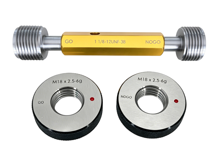
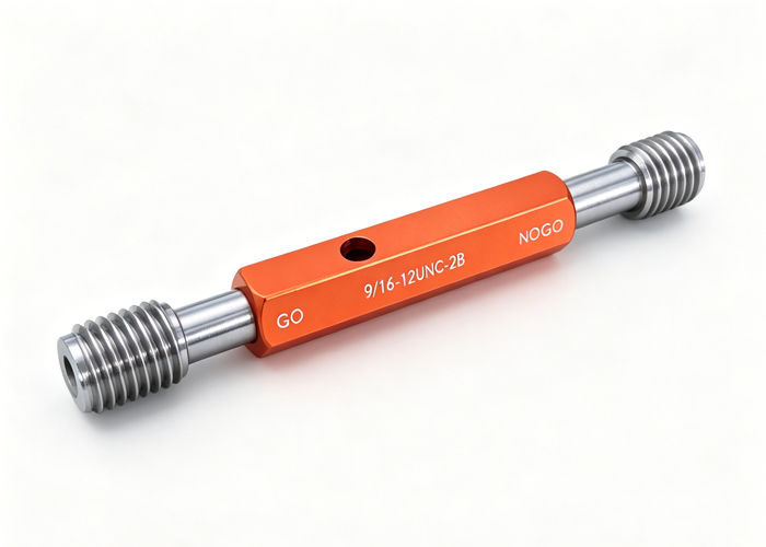
A precision thread ring gauge inspects the functional diameter of an external screw thread by integrating pitch diameter, lead angle, flank geometry, and taper into a single engagement check. If a “Go” ring gauge cannot thread smoothly along the full functional length of a bone screw without forced torque, the screw will likely jam or generate excessive friction when driven into target plate holes or tapped bone channels.
Conversely, the “No-Go” gauge validates that the pitch diameter has not fallen below lower material limits. This rapid physical gating provides immediate pass/fail feedback at the machine tool without the processing latency of loading individual micro-fasteners onto high-magnification optical stages.
Addressing Asymmetric Threads, Micro Pitches, and Self-Tapping Flutes
Most orthopedic bone screws incorporate cutting flutes at their tip to enable self-tapping insertion during surgery. These flutes interrupt the continuous thread helix, creating sharp lead-in edges.
When deploying calibrated thread gauges across self-tapping sections:
Gauging must evaluate both the fluted zone and the continuous body thread without binding against burrs generated during flute milling.
Operators must not confuse entry-burr resistance with genuine pitch diameter boundaries.
Thread forms featuring asymmetric load flanks require dedicated, custom-ground gauges that mirror the exact pressure angle and clearance radius specified on the engineering print.
Preventing Galling and False Rejections: Material and Surface Considerations for Medical Gauging
Galling poses a constant threat during the physical inspection of titanium and cobalt-chromium medical screws. Titanium exhibits high chemical affinity and frictional adhesion when brought into dry contact with steel or carbide tools. Without controlled inspection practices, repeated metal-on-metal contact can weld micro-particles to the gauge flank, causing localized scoring on the implant and accelerating gauge wear.
Titanium & Cobalt-Chrome Sensitivity: Minimizing Tool Contact Friction
To prevent galling, metal pickup, and false part rejection:
Controlled Engagement Velocity: Gauges must be threaded by hand or with calibrated torque-limiting inspection drivers at steady, moderate speeds.
Surface Finishes and Substrates: Selecting high-grade tool steels or tungsten carbide substrates with ultra-fine, polished thread flanks reduces surface friction during contact.
Residual Cleanliness: Gauges and machined screws must be thoroughly degreased prior to inspection. Particulate matter, cutting oils, and micro-swarf accelerate abrasive wear on the measuring flanks.
Cleanroom Protocols and Gauge Calibration Drift
Medical machining environments typically require strict cleaning, passivating, and packaging steps. Thread gauges used adjacent to or inside controlled cleanroom environments must be monitored for calibration drift:
Thermal Equilibrium: Thread ring and plug gauges must acclimate to the inspection room ambient temperature (typically 20°C / 68°F) before use, as micro-scale tolerances can shift with minor thermal expansion.
Wear Allowance Tracking: Medical quality systems must define strict maximum wear allowances. When a “No-Go” gauge allows entry beyond allowable turns due to flank wear, or a “Go” gauge drops below its minimum wear limit, it must be removed from production immediately.
Standard vs. Custom Thread Gauges: Engineering Solutions for Proprietary Medical Fasteners
While conventional medical devices occasionally use standardized miniature UN, Metric, or Whitworth forms, most bone screws, spinal screws, and dental abutments use specialized thread profiles tailored to proprietary surgical systems.
| Feature Comparison | Standard Thread Profiles (Metric / UN) | Proprietary Bone Screw Profiles |
| Profile Geometry | Symmetric 60° flank angles with standard crest truncations | Asymmetric flanks (e.g., 30°/5°), buttress forms, or variable leads |
| Root Radii | Standard commercial root radii | Enlarged, controlled root radii to minimize surgical fatigue failure |
| Tolerance Class | Common industrial limits (Class 2A/2B, 3A/3B, 6g/6H) | Application-specific micro-tolerances matched to implant interfaces |
| Inspection Tooling | Catalog standard thread plug and ring gauges | Custom-ground gauges manufactured directly to OEM part drawings |
| Quality Objective | Inter-brand interchangeability and standard assembly | Targeted biological anchoring and high pull-out resistance |
When ordering custom tooling, quality engineers should provide complete part prints detailing major, pitch, and minor diameters, flank angles, root radii, and allowable thread runout to ensure matching gauge tolerances.
Standard Operating Procedure: Deploying Thread Gauges in Bone Screw Production Lines
To maintain repeatable inspection data across multiple production shifts, operators should follow a documented standard operating procedure (SOP) for fixed-limit gauging:
Step 1: Cleaning and Pre-Inspection Verification
Clean the screw thoroughly using an ultrasonic solvent bath or approved degreaser to remove machining coolants, fine titanium chips, and surface contaminants. Inspect the screw under low magnification to verify that thread starts and self-tapping flutes are free of burrs.
Step 2: “Go” Gauge Functional Check
Align the calibrated “Go” thread ring gauge coaxially with the screw axis.
Engage the gauge using light, two-finger manual pressure without forcing the tool.
The “Go” gauge must spin freely over the complete functional length of the thread. Any premature binding or rough resistance indicates pitch diameter oversize, lead error, excessive root material, or damage on the part’s thread crests.
Step 3: “No-Go” Gauge Boundary Check
Present the calibrated “No-Go” thread ring gauge to the screw.
Attempt engagement using the same two-finger manual pressure.
Engagement must not exceed defined quality limits—typically no more than two complete turns before seating or stopping, depending on the internal QA manual. Complete engagement indicates that the screw is undersized (pitch diameter too small), compromising pull-out strength.
Step 4: Gauge Cleaning and In-Process Storage
Wipe the gauge with a lint-free cloth, inspect the lead threads for metal pickup, and return the tool to its dedicated protective case. Never store loose gauges alongside parts, cutting tools, or metal fixtures.
Securing Zero-Defect Precision: Working with Precision Tooling Partners
Implementing a zero-defect quality architecture for bone screws and orthopedic hardware requires reliable physical gauging tools that hold consistent geometry over repeated inspection cycles. Partnering with specialized tooling manufacturers ensures that every set of thread gauges provides the micro-inch accuracy, surface finish, and dimensional stability demanded by medical device manufacturing.
Whether qualifying standard machine screws or implementing dedicated inspection protocols for proprietary implants, validated gauging tools protect patient safety and mitigate the risks of costly production rejections.
Key Takeaways
Functional Engagement: While optical systems measure isolated geometric parameters, physical thread gauges provide the primary check for complete, three-dimensional functional assembly.
Galling Management: Titanium implants require smooth gauge surfaces, clean contact areas, and controlled manual handling to prevent metal transfer and false rejections.
Custom Tooling Requirements: Non-standard bone screw thread designs (including asymmetric buttress forms and variable leads) require custom-ground gauges built to matched part prints.
Dual-Track Quality Strategy: Combining 100% rapid shop-floor ring-gauge testing with periodic optical metrology ensures zero-defect quality and full regulatory traceability.
Frequently Asked Questions (FAQ)
How often should thread ring gauges be recalibrated in high-volume medical screw machining?
Recalibration intervals depend on production volume, part material, and inspection frequency. While steel fasteners allow longer calibration cycles, abrasive and galling-prone materials like titanium wear gauges more rapidly. High-volume implant lines typically recalibrate or verify working gauges against master setting plugs weekly or monthly, backed by formal calibration records.
Can physical thread gauges damage cannulated bone screws?
Cannulated screws feature a central hollow bore designed for guidewires, which thins the wall thickness beneath the thread root. Excessive force during gauge engagement can distort these thin walls. Using hand verification without forced torque, verifying concentricity, and maintaining clean gauge surfaces prevents mechanical damage to delicate hollow parts.
What documentation is required for thread gauges during an ISO 13485 or FDA inspection audit?
Auditors require documented proof that all measuring equipment affecting product safety is tracked and calibrated. This includes traceable calibration certificates tied to national standards, defined calibration schedules, unique gauge serial numbers, documented wear limits, and logs detailing out-of-tolerance quarantines.