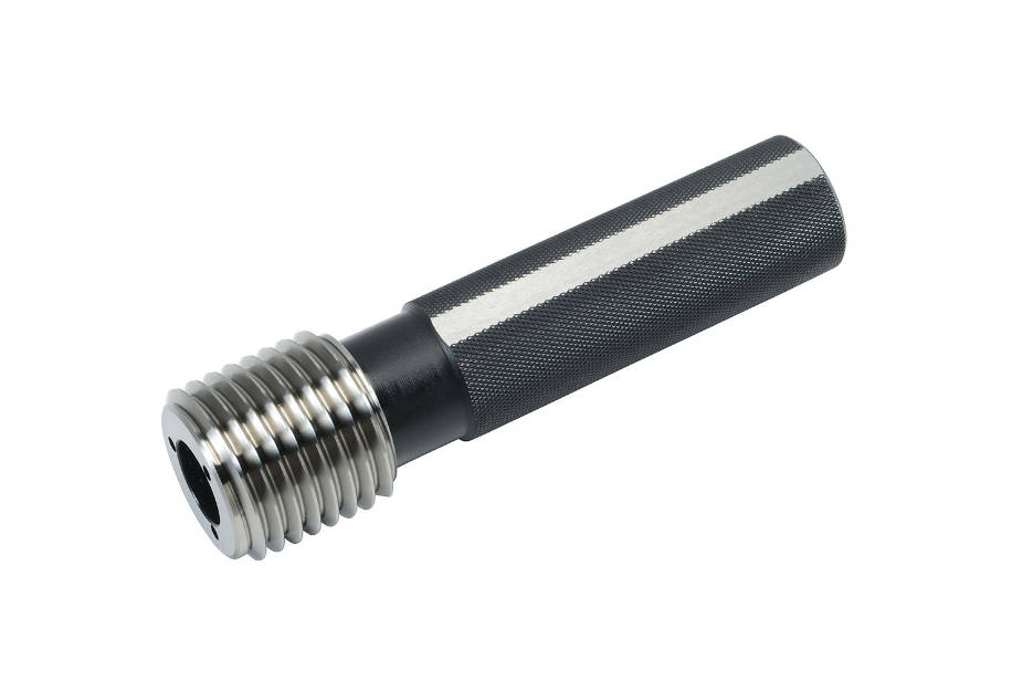
Precision thread gauges are fixed-limit inspection tools engineered to verify that threaded fasteners, tapped holes, and machined components match their specified pitch diameter, thread profile, and tolerance limits. Selecting the right gauging system requires matching your component’s thread standard (such as ISO Metric, Unified National, or pipe threads), verifying the required class of fit, and choosing a gauge material that withstands your daily inspection cycle count.
This guide outlines the operational differences between plug and ring gauges, analyzes international tolerance standards, details wear resistance across tool materials, and provides a structured procurement framework for manufacturing and quality assurance operations.
The Critical Role of Precision Thread Gauges in Modern Quality Control
In high-precision manufacturing—spanning automotive assemblies, aerospace hydraulics, and fluid conduit systems—thread failure frequently traces back to pitch diameter deviations rather than gross dimensional errors. While coordinate measuring machines (CMM) and optical profile projectors deliver comprehensive dimensional analysis, they are often throughput bottlenecks in high-volume production.
Precision thread gauges provide rapid, deterministic Go/No-Go verification directly on the shop floor. They inspect the cumulative functional interaction of multiple thread elements simultaneously:
Pitch Diameter: The theoretical cylinder where the widths of the thread ridge and groove are equal.
Lead and Pitch: The linear advance per turn and the spacing between adjacent crests.
Flank Angle: The angle formed between the thread flank and the axis perpendicular to the thread centerline.
Major and Minor Diameters: The absolute crest and root boundaries that govern assembly clearance.
By verifying functional fit within seconds, physical limit gauges safeguard assembly lines against thread galling, cross-threading, and loose fasteners before components reach secondary assembly stages.
Core Types of Thread Gauges: Plug, Ring, and Calipers
Thread inspection divides fundamentally into internal (female) and external (male) thread verification. Using the correct gauge type prevents false acceptance of out-of-spec parts.
Thread Plug Gauges: Verifying Internal Threads
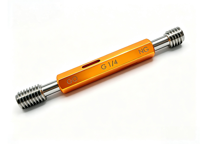
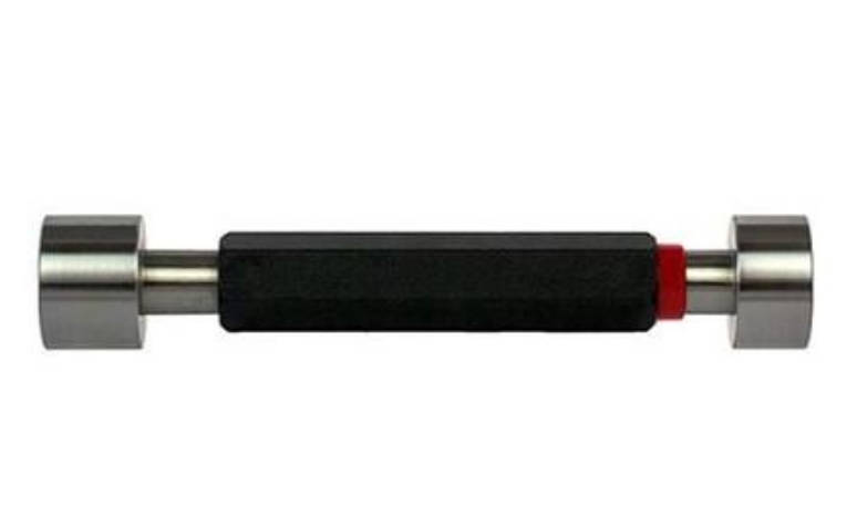
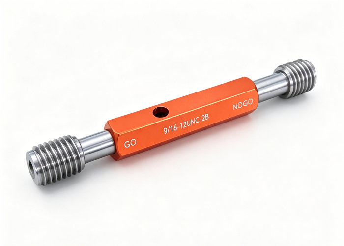
A thread plug gauge inspects internally tapped holes, nuts, and manifold ports. Standard working plug gauges feature a double-ended design fitted into a hex-swivel handle:
Go Member: Engineered to evaluate maximum material condition (MMC). The Go plug verifies that the internal thread pitch diameter is not undersized and that lead, angle, and root clearances allow full thread engagement. It must thread completely into the part without excessive force.
No-Go Member: Engineered to evaluate minimum material condition (LMC). The No-Go plug verifies that the pitch diameter is not oversized, which would compromise thread shear strength. Under standard inspection protocols, it must not engage the tapped hole by more than two to three turns.
Thread Ring Gauges: Inspecting External Threads
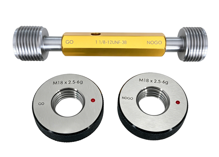
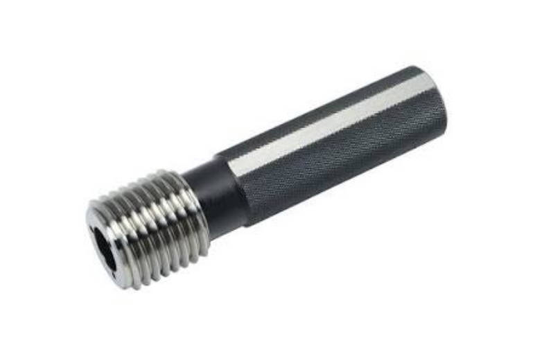
Thread ring gauges verify externally threaded components such as machine screws, studs, turned bolts, and threaded pipe fittings. Unlike plug gauges, thread ring gauges are individual solid or adjustable rings:
Go Ring Gauge: Evaluates external thread MMC. It checks that the external pitch diameter and major diameter do not exceed allowable limits. The Go gauge must pass freely over the entire active thread length.
No-Go Ring Gauge: Evaluates external thread LMC. It checks that pitch diameter is not under the allowable minimum, preventing loose fits. It must not advance beyond two to three turns onto the component.
The Engineering Logic Behind Go / No-Go Limits
| Gauge Type | Primary Target | Inspected Condition | Pass Criteria | Typical Failure Mode Identified |
| Go Thread Plug | Internal Threads (Tapped holes, nuts) | Maximum Material Condition (MMC) | Enters full depth smoothly without binding | Undersized pitch diameter; lead error; flank angle distortion |
| No-Go Thread Plug | Internal Threads (Tapped holes, nuts) | Least Material Condition (LMC) | Does not enter past 2–3 turns | Oversized pitch diameter; stripped/worn tap profile |
| Go Thread Ring | External Threads (Bolts, studs, pipes) | Maximum Material Condition (MMC) | Runs smoothly over the entire thread length | Oversized pitch diameter; burrs on crests; pitch stretch |
| No-Go Thread Ring | External Threads (Bolts, studs, pipes) | Least Material Condition (LMC) | Stops within 2–3 turns | Undersized pitch diameter; excessive material removal |
Navigating Standards: Metric, Unified (UN/UNF), and Pipe Threads
Applying the correct metrology standard prevents costly cross-standard mismatches. Each standard defines distinct flank angles, clearance roots, and tolerance bands.
Thread Standards Technical Comparison
| Parameter / Feature | Metric (ISO 1502) | Unified National (ASME B1.1) | NPT Pipe (ASME B1.20.1) |
| Flank Angle | 60° symmetrical profile | 60° symmetrical profile | 60° flank angle |
| Crest / Root Geometry | Flat crests, rounded roots | Flat crests, rounded roots | Flat crests and roots (truncated) |
| Taper Ratio | Straight / Parallel (0 taper) | Straight / Parallel (0 taper) | Tapered 1:16 (3/4 in/ft on diameter) |
| Typical Tolerance Classes | 6H (internal) / 6g (external) | 2B, 3B (internal) / 2A, 3A (external) | L1 hand-tight reference engagement |
| Primary Metric Gauged | Functional pitch diameter limits | Functional pitch diameter limits | Standoff notch depth position (±1 turn) |
Metric Thread Standards (ISO 1502)
Metric threads utilize a 60-degree symmetrical triangular profile with flat crests and rounded roots.
Standard designations (e.g., M10 x 1.5 – 6H) indicate nominal diameter, pitch, and tolerance class.
Capital letters denote internal thread tolerances (e.g., 6H, 7H), with H representing zero fundamental deviation (basic pitch diameter at minimum limit).
Lowercase letters denote external thread tolerances (e.g., 6g, 6e), with g indicating a positive clearance allowance to accommodate plating or thermal expansion.
Unified National Series (UNC, UNF, UNEF – ASME B1.1)
The Unified standard governs inch-based fasteners utilizing a 60-degree thread form.
UNC (Coarse): Designed for rapid assembly, general machinery, and softer parent materials like aluminum and cast iron.
UNF (Fine): Features a smaller lead angle and shallower thread depth, providing greater tensile stress area and resistance to vibrational loosening in structural and automotive applications.
Classes of Fit:
Class 1A / 1B: Loose fit with generous clearance for rapid assembly in dirty or abrasive environments.
Class 2A / 2B: Standard commercial fit used across the majority of industrial fasteners, bolts, and tapped holes.
Class 3A / 3B: Tight, zero-allowance fit required for high-stress aerospace, defense, and precision tooling assemblies where backlash cannot be tolerated.
Tapered and Straight Pipe Threads (NPT vs. BSPT)
Pipe thread inspection differs from standard parallel threads because fluid-tight joints depend on mechanical wedging along a controlled taper:
NPT (ASME B1.20.1): Features a 60-degree thread angle and a 1:16 taper ratio along the diameter (3/4 inch per foot). Inspection uses an L1 Step Plug or Ring Gauge to evaluate hand-tight engagement depth. The pipe end must seat flush within the gauge’s precision-ground notch tolerance window (typically ±1 turn from the basic step).
BSPT / ISO 7-1 (British Standard Pipe Taper): Employs a 55-degree Whitworth thread angle with rounded crests and roots and the same 1:16 taper. Gauges for BSPT and NPT are not interchangeable due to the flank angle mismatch.
Downstream Production Context: In continuous fluid conduit and line manufacturing—such as specialized pipe profiles produced along an extrusion line—inline or station-based thread gauging confirms that downstream threaded connectors, couplings, and transition fittings maintain pressure seal integrity under working mechanical loads.
Tool Metallurgy: Choosing the Right Material for Durability
Gauges undergo repeated friction and abrasive contact against machined workpieces. Selecting an improper gauge material results in premature wear, rapid calibration loss, and false rejects.
| Gauge Material / Treatment | Hardness Range | Optimal Production Volume | Key Technical Advantages | Primary Limitations |
| Hardened Tool Steel (GCr15) | 58–62 HRC | Low to Medium (< 500 cycles/month) | Economical, widely available for standard sizes, good base stability | Wears rapidly on abrasive cast irons or stainless steels |
| Tungsten Carbide | 88–92 HRA | High-Volume (> 5,000 cycles/month) | 10x to 30x wear resistance over tool steel, extreme profile stability | Higher initial acquisition cost; vulnerable to chipping if dropped |
| PVD Coatings (TiN / Chrome) | > 2000 HV (Surface layer) | Medium to High-Wear Lines | Low surface friction, galling resistance, protection against corrosion | Added processing lead time; thin coating can chip under severe impact |
Hardened Tool Steel (Bearing Steel / GCr15)
Standard thread gauges are typically manufactured from through-hardened alloy tool steel or bearing-grade high-carbon chromium steel (GCr15), tempered to 58–62 HRC.
Advantages: Cost-effective, readily available across all standard pitch sizes, and provides sufficient stability for general machine shop inspection.
Limitations: Prone to premature abrasive wear when inspecting unwashed castings, cast iron, stainless steel, or abrasive fiber-filled composites.
Tungsten Carbide for High-Volume Production Runs
Carbide thread gauges feature solid tungsten carbide or carbide-inserted pitch sections, delivering hardness levels around 88–92 HRA.
Advantages: Offers 10 to 30 times the wear resistance of conventional tool steel. It maintains dimensional stability over extensive inspection cycles in automated automotive, fastener, and high-volume stamping lines.
Limitations: Higher initial acquisition cost; vulnerable to chipping if dropped or subjected to heavy impacts.
Surface Coatings: Titanium Nitride (TiN) and Hard Chrome Plating
Where solid carbide is cost-prohibitive for large-diameter threads, applied thin-film physical vapor deposition (PVD) coatings provide an effective barrier:
Titanium Nitride (TiN): Yields a distinct gold surface with micro-hardness exceeding 2000 HV, drastically reducing frictional drag and galling on stainless steel fasteners.
Hard Chrome Plating: Enhances corrosion resistance and serves as a low-friction protective layer for non-ferrous and marine component inspection.
How to Select the Correct Thread Gauge: Engineering Decision Framework
To eliminate procurement errors and operational delays, use this four-step decision matrix before ordering thread gauges.
Step 1: Identify Thread Form and Pitch Profile
Determine whether the target component has standard parallel threads (ISO Metric, UNC/UNF) or tapered pressure-tight threads (NPT, BSPT). Measure or specify nominal major diameter, pitch (or threads per inch – TPI), and hand direction (right-hand standard vs. left-hand LH).
Step 2: Define Fit Class and Post-Plating Allowances
Match the component’s required functional fit (e.g., 6H for an internal metric thread or 2A for an external unified bolt).
Critical Check: Determine whether the thread will undergo secondary surface treatments such as electroplating, anodizing, or hot-dip galvanizing. Plating deposits 3 to 15 microns of surface thickness, reducing internal hole diameters while enlarging external bolt diameters. In such cases, specify special pre-plate gauge pitch diameters to prevent post-treatment assembly interference.
Step 3: Assess Production Volume and Gauging Frequency
Fewer than 500 inspections/month: Standard hardened tool steel (GCr15) delivers adequate service life at minimal capital cost.
More than 5,000 inspections/month: Tungsten carbide is the more cost-effective choice over the tool’s lifecycle by drastically extending recalibration intervals.
Step 4: Distinguish Working Gauges from Master Setting Gauges
Working Gauges: Used directly on machine lines and quality inspection benches to inspect parts.
Setting Masters (Trun-Type or Master Thread Plugs): Used exclusively in calibration laboratories to adjust, zero, and verify mechanical thread ring gauges and calipers. Never introduce setting plugs onto daily shop-floor inspection lines.
Maintenance, Calibration, and Wear Limits
Thread gauges degrade through physical contact. Implementing consistent metrological hygiene ensures measurements remain legally and operationally defensible.
Calibration Frequency Based on Production Volume
Calibration intervals should be determined by actual cycle counts rather than arbitrary calendar intervals:
High-Throughput In-Line Inspection: Gauge verification every 30 to 90 days.
Batch / Pilot Inspection: Six-month to one-year calibration intervals.
Every calibrated gauge must be traced to regional or international metrology standards (such as ISO 17025 accredited calibration protocols) with certified pitch diameter values recorded.
Cleaning and Storage Protocols
Avoid Forced Insertion: Gauges must rotate smoothly using thumb-and-finger torque. Forcing a Go gauge can damage the component and permanently deform the gauge’s lead pitch.
Clean Components Before Inspection: Metal swarf, cutting fluids, and abrasive grinding dust act as lapping compounds inside ring and plug gauges, accelerating pitch erosion.
Thermal Normalization: Conduct precision inspections at a baseline room temperature of 20°C (68°F). Large aluminum components and high-mass steel gauges exhibit divergent thermal expansion coefficients that can induce false gauge rejections in non-climate-controlled plants.
Corrosion Inactivation: When storing tool steel gauges, degrease, dry, and apply a micro-film rust preventative before placing them in molded protective storage boxes.
When to Retire a Thread Gauge
A thread gauge has reached its wear limit and must be removed from production when:
The Go Member Pitch Diameter Wears Below Minimum: The tool steel profile thins, allowing undersized internal or oversized external threads to pass inspection.
The No-Go Member Pitch Diameter Wears Beyond Limit: A damaged or ground-down No-Go member begins engaging past the permitted three-turn threshold on valid parts.
Flank Binding Occurs Due to Dropping: Dropped gauges with dented lead chamfers generate burrs that bite into test pieces regardless of dimensional accuracy.
Custom Thread Gauges: Technical Sourcing Checklist for B2B Buyers
Specialty machinery, hydraulic blocks, and downhole components often feature proprietary, multi-start, or non-standard thread designs. When requesting custom tooling from a precision gauge manufacturer, prepare the following engineering inputs:
| Sourcing Parameter | Required Specification Detail | Example Engineering Input |
| 1. Nominal Size & Designation | Full engineering designation | M42 x 1.25 Special / 1-1/8-12 UNF |
| 2. Pitch / Lead Specifics | Exact pitch in mm or TPI; lead distance | 1.25 mm Pitch (Single start) or Multi-start Lead |
| 3. Thread Form Profile | Profile angle and root/crest standards | Standard 60° V-profile, 29° Acme, Trapezoidal |
| 4. Fit Class & Tolerance Limits | Explicit tolerance class or pitch dia range | Class 6H, Class 2A, or specified micron boundaries |
| 5. Surface Condition Stage | Pre-plate or final post-plate dimensions | Pre-plate (account for 8 μm zinc plating) |
| 6. Gauge Architecture | Functional gauge layout | Double-ended plug, single-ended ring, taper plug |
| 7. Substrate Material | Material matching production volume | GCr15 Tool Steel or Solid Tungsten Carbide |
| 8. Calibration Credentials | Required metrological trace level | ISO 17025 accredited calibration certificate |
Manufacturers like Mihe engineer custom limit gauges to micron-level tolerances, delivering traceable calibration documentation for complex profiles, multi-start leads, long-reach blind holes, and non-standard pitch diameters.
Key Takeaways
Inspection Function: Thread plug gauges verify internal female threads, while thread ring gauges verify external male threads using complementary Go and No-Go pitch profiles.
Go vs. No-Go Limits: The Go gauge verifies Maximum Material Condition (must advance smoothly full depth); the No-Go gauge verifies Least Material Condition (must not seat beyond 2 to 3 full revolutions).
Tolerance Consistency: Never interchange standards. Metric (6H/6g) and Unified (2B/2A, 3B/3A) feature distinct geometric foundations, while tapered pipe joints (NPT/BSPT) require step-notched depth verification.
Substrate Strategy: Standard tool steel (GCr15) serves general fabrication runs, while tungsten carbide provides the lowest cost per inspection in automated, high-volume manufacturing lines.
Coating Compensation: Specify whether dimensions are required for pre-plate or post-plate inspection to prevent interference once surface finishes are applied.
FAQ
Can a thread ring gauge be repaired once it wears past its tolerance limit?
Solid thread ring gauges cannot be reliably rebuilt once the pitch diameter wears beyond allowable limits; they must be decommissioned and replaced. However, adjustable thread ring gauges feature a radial adjusting screw and locking mechanism that allows an accredited calibration lab to resize the gauge over a master setting plug, restoring compliance within specified limits.
What is the primary difference between Class 2A/2B and Class 3A/3B thread gauges?
Class 2A (external) and 2B (internal) represent standard commercial fastener fits with a moderate allowance that accommodates typical plating thicknesses and assembly variations. Class 3A and 3B represent zero-allowance, close-tolerance fits engineered for aerospace, engine internals, and high-performance assemblies where backlash, play, and runout must be tightly controlled.
Why does a Go plug gauge bind even when the tapped hole’s major diameter measures correct?
A hole’s major and minor diameters can fall within standard limits while its pitch diameter, flank angle, or thread lead is out of specification. If the lead is stretched or the tap was misaligned (angled entry), the functional diameter contracts, causing the Go gauge to bind. A thread plug gauge evaluates the collective geometry, preventing bad assemblies that simple bore calipers miss.
How do ambient shop temperatures affect thread gauging accuracy?
Steel gauges and test components expand or contract with temperature fluctuations. If inspecting components made from dissimilar metals (such as aluminum workpieces checked with steel gauges), a 10°C departure from the metrological standard of 20°C (68°F) can induce noticeable dimensional divergence, causing false rejects or unmerited approvals.