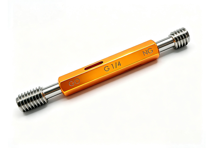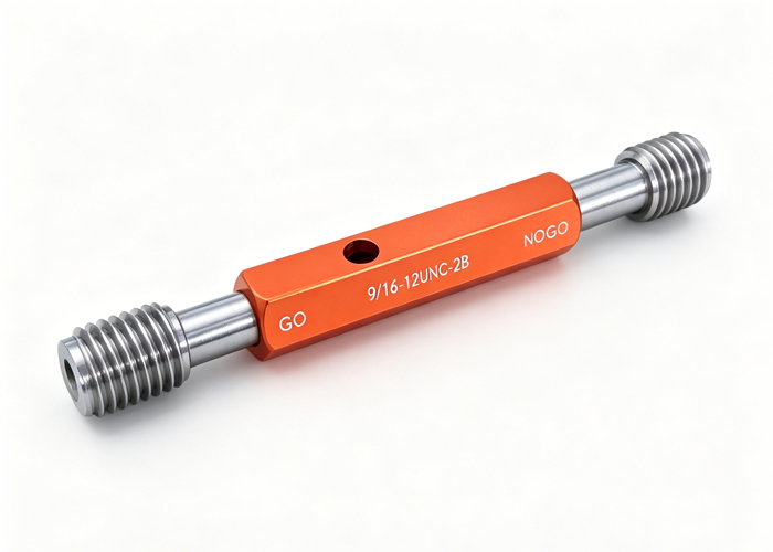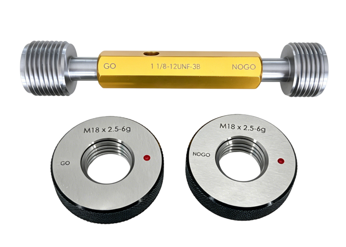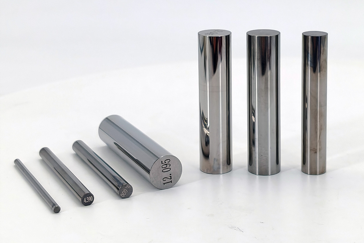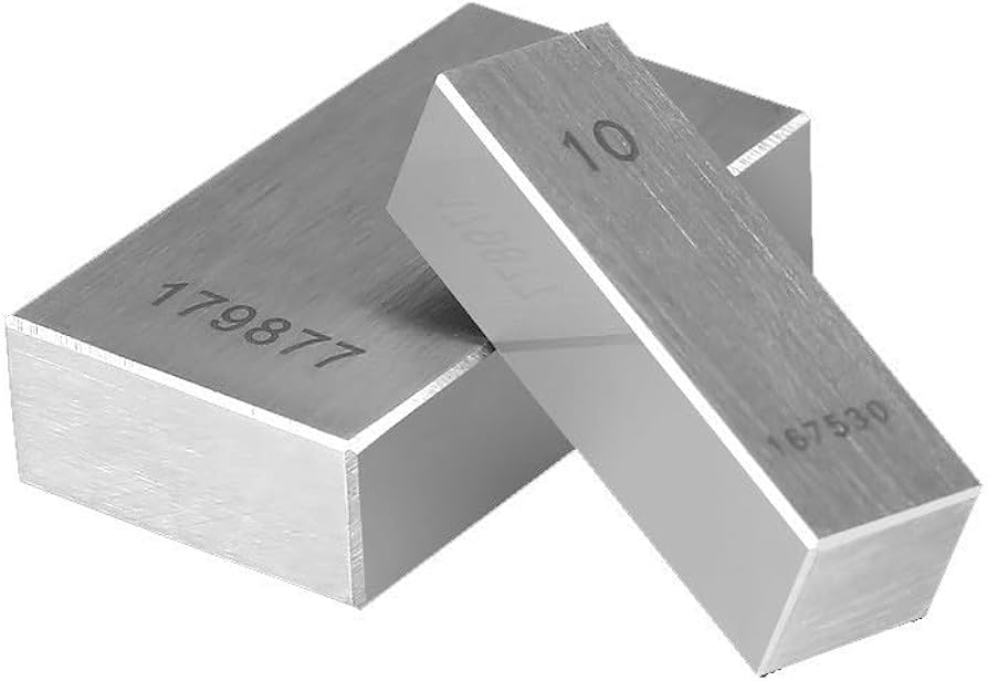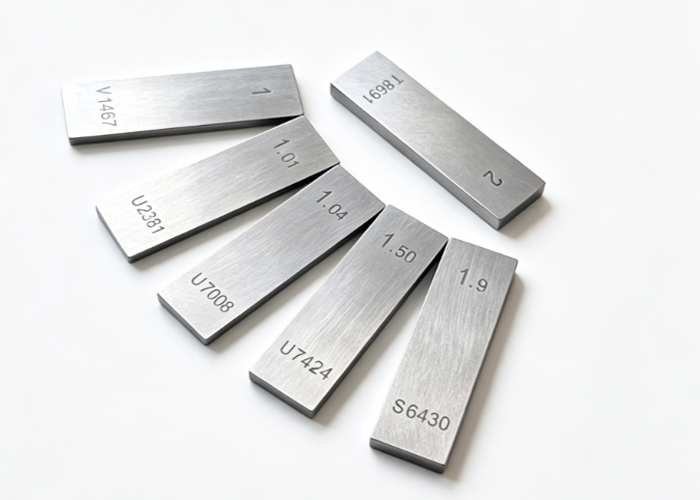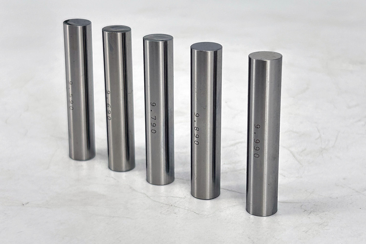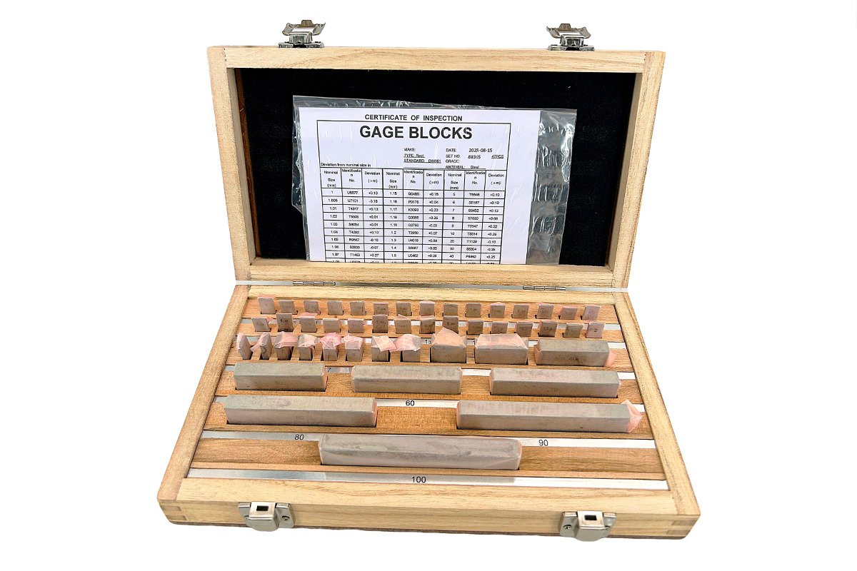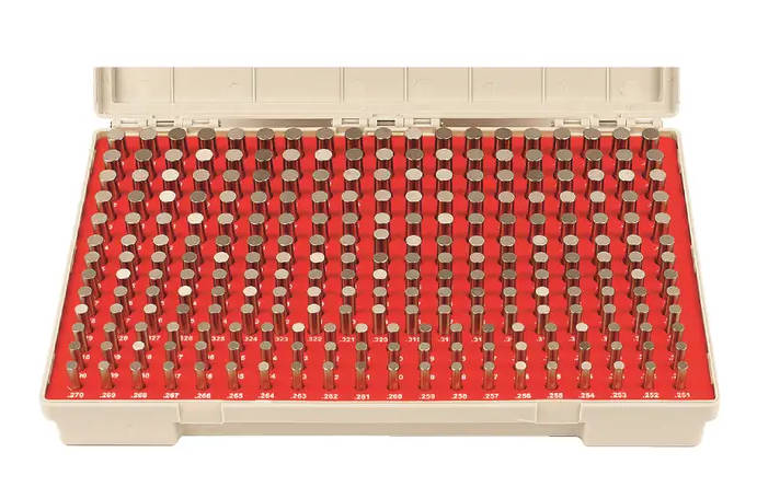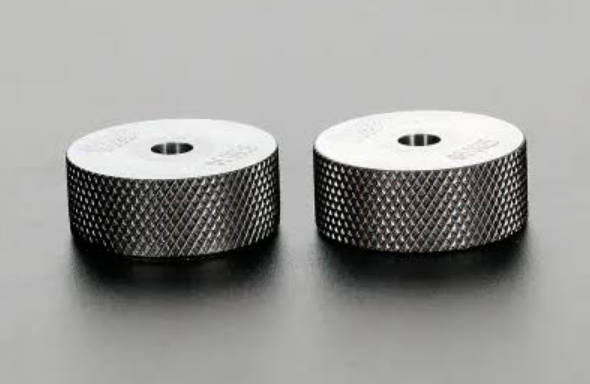
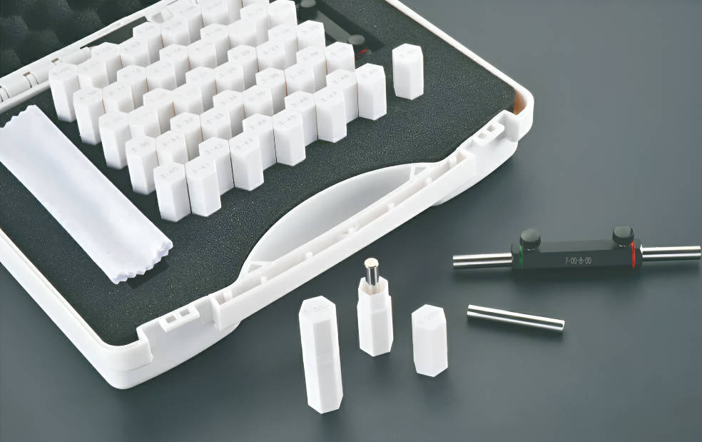
Pin gauges are used to check hole diameter by inserting precision cylindrical pins into a hole and identifying which pin size fits correctly. A pin gauge does not always give a full geometric measurement like a CMM or bore gauge, but it provides a fast and practical way to verify whether a hole is within a required size range.
In manufacturing, pin gauges are widely used for hole inspection, slot width checking, gap measurement, alignment verification, and Go/No-Go inspection. A pin gauge set, also called a pin gage set, includes many precision pins with controlled diameters. By testing different sizes, inspectors can estimate the hole size or confirm whether the hole meets the tolerance requirement.
For CNC machining, mold manufacturing, precision hardware, automotive parts, and medical components, hole diameter measurement is not just a basic inspection step. It can directly affect assembly fit, shaft clearance, fastener performance, airflow, fluid passage, and product function.
MISHUTE supplies pin gauges for precision inspection applications. You can review related options on the MISHUTE pin gauges page.
What Is a Pin Gauge?
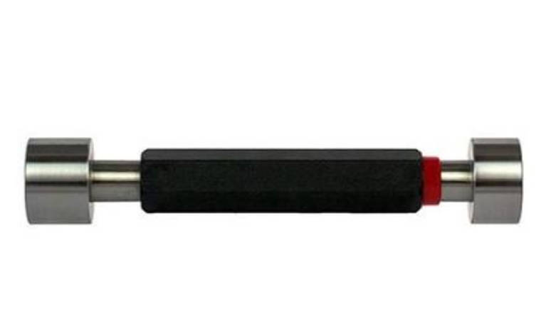
A pin gauge is a precision cylindrical gauge with a known diameter. It is used as a reference size for checking holes, slots, grooves, gaps, and other internal features.
Pin gauges are commonly used to inspect:
- Hole diameter
- Hole size tolerance
- Slot width
- Groove width
- Gap size
- Hole location
- Bore straightness
- Small internal features
- Go/No-Go acceptance conditions
- Machining consistency across batches
The basic principle of a pin gauge is simple: if a known-size pin fits into a hole, the hole is at least that size under the inspection condition.
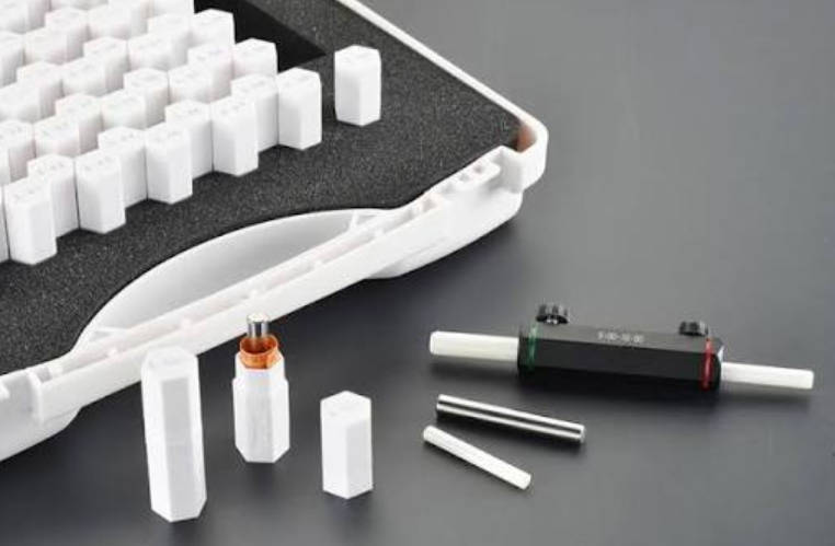
Pin gauges are usually supplied as sets with small diameter increments. This allows inspectors to test a sequence of pins and determine which size passes or fails.
How Pin Gauges Measure Hole Diameter
Pin gauges measure hole diameter through fit comparison. Instead of reading a digital number from a measuring instrument, the inspector checks whether a physical pin can enter the hole.
The common process is:
- Select a pin close to the expected hole size.
- Clean the pin and the hole.
- Insert the pin straight into the hole.
- Check whether the pin enters smoothly.
- Try the next larger or smaller pin if needed.
- Record the largest pin that enters or the Go/No-Go result.
- Compare the result with the drawing tolerance.
When using pin gauges to estimate hole diameter, the largest pin that enters smoothly usually indicates the minimum functional size that the hole can accept.
However, this does not mean the hole is perfectly round, straight, or uniform. A pin gauge gives useful functional information, but it does not fully describe all geometry errors.
Pin Gauge Measurement vs Actual Diameter Measurement
A pin gauge is not the same as a bore gauge, air gauge, or CMM. Each tool has a different purpose.
| Tool | What It Provides | Best Use |
| Pin gauge | Fit/no-fit or approximate hole size | Fast hole checking and Go/No-Go inspection |
| Bore gauge | Actual diameter variation | Measuring internal diameter with higher detail |
| Air gauge | High-resolution comparative measurement | Precision bore measurement in production |
| CMM | Coordinate and geometric measurement | Position, roundness, profile, and complex inspection |
| Caliper | General size measurement | Less suitable for small precision holes |
| Plug gauge | Fixed-limit hole acceptance | Fast pass/fail inspection |
A pin gauge is useful because it is simple, repeatable, and fast. But if you need actual roundness, cylindricity, taper, or full profile data, a different measuring method may be required.
Step-by-Step: How to Use Pin Gauges for Hole Diameter Measurement
Step 1: Read the Drawing Requirement
Before selecting a pin gauge, confirm the drawing information:
- Nominal hole diameter
- Upper tolerance
- Lower tolerance
- Unit system: metric or inch
- Through hole or blind hole
- Hole depth
- Surface finish requirement
- Part material
- Inspection standard
- Whether the hole is functional or clearance-based
For example:
| Drawing Item | Example |
| Nominal hole size | Ø8.000 mm |
| Lower limit | Ø7.990 mm |
| Upper limit | Ø8.010 mm |
| Tolerance range | 0.020 mm |
| Inspection target | Confirm acceptable hole size |
The inspection method should be based on the tolerance limits, not only the nominal size.
Step 2: Clean the Hole and Pin Gauge
Dirt, oil, burrs, chips, coating, or coolant residue can affect the inspection result. A hole that is actually acceptable may fail if debris blocks the pin. A hole that is damaged may appear acceptable if the inspector forces the pin.
Recommended practice:
- Clean the hole before checking
- Remove chips and burrs if the inspection procedure allows
- Wipe the pin gauge clean
- Avoid using damaged or rusty pins
- Check that the pin is not bent or worn
- Use consistent inspection conditions
A pin gauge should be inserted into a clean hole with light, controlled hand pressure. It should not be forced.
Step 3: Start with a Reasonable Pin Size
If the expected hole size is known, start near the nominal diameter or near the tolerance limit you want to check.
For approximate hole size measurement:
- Start slightly smaller than the expected diameter.
- Increase pin size step by step.
- Find the largest pin that enters smoothly.
- Use the next larger pin to confirm that it does not enter.
For Go/No-Go inspection:
- Use the GO pin to check the minimum acceptable hole condition.
- Use the NO-GO pin to check the maximum acceptable hole condition.
Step 4: Insert the Pin Straight
Alignment matters. If the pin enters at an angle, the result may be misleading. This is especially important for small holes, deep bores, and tight tolerances.
Good technique:
- Hold the pin straight with the hole axis.
- Do not rock the pin aggressively.
- Avoid side loading.
- Use light hand pressure.
- For deep holes, check whether the pin travels through the required depth.
- For blind holes, confirm the required insertion depth.
If a pin only enters at an angle or requires force, the hole should not automatically be accepted.
Step 5: Interpret the Fit
The fit should be judged consistently. The meaning of “fits” should be defined by your quality procedure.
| Fit Condition | Possible Meaning |
| Pin enters smoothly | Hole is at least that pin size |
| Pin does not enter | Hole may be smaller than that pin size |
| Pin enters only with force | Result is questionable; recheck |
| Pin enters partially | Possible taper, burr, debris, or depth issue |
| Pin rocks excessively | Hole may be oversize or out of round |
| Pin fits at one angle only | Possible form error or burr |
For production inspection, operators should not make personal judgments each time. The inspection method should define what counts as acceptable fit.
Go/No-Go Pin Gauge Method
Pin gauges are often used as Go/No-Go gauges. This is especially useful when the goal is to accept or reject a part, not to find the exact diameter.
| Gauge Type | Function | Expected Result |
| GO pin | Checks whether the hole is large enough | Should enter |
| NO-GO pin | Checks whether the hole is not too large | Should not enter |
| Pass condition | GO enters and NO-GO does not enter | Hole is acceptable |
| Fail condition 1 | GO does not enter | Hole may be too small |
| Fail condition 2 | NO-GO enters | Hole may be too large |
For Go/No-Go hole inspection, the GO pin should enter the hole, while the NO-GO pin should not enter under the defined inspection condition.
This method is widely used in high-volume production because it is fast and reduces the need for reading numerical measurement values.
Plus and Minus Pin Gauges Explained
Pin gauges may be supplied with plus, minus, or bilateral tolerance. Understanding this is important when selecting a pin gage set.
Plus Pin Gauges
A plus pin gauge is made so that its actual diameter is slightly above the nominal size within its tolerance. Plus pins are commonly used as GO gauges for certain inspection strategies because they help ensure the hole is not undersized.
Minus Pin Gauges
A minus pin gauge is made so that its actual diameter is slightly below the nominal size within its tolerance. Minus pins are commonly used as NO-GO gauges in some limit inspection systems.
Bilateral Pin Gauges
Bilateral pin gauges have tolerance distributed around the nominal size. They may be used for general measurement or reference applications depending on the inspection requirement.
| Pin Gauge Type | Typical Use | Selection Concern |
| Plus pin gauge | GO inspection in many systems | Confirms hole is not too small |
| Minus pin gauge | NO-GO inspection in many systems | Helps check maximum hole limit |
| Bilateral pin gauge | General measurement/reference use | Must match inspection method |
| Custom tolerance pin | Special drawing or customer requirement | Requires clear specification |
The correct tolerance direction should be confirmed with your quality standard, customer requirement, or gauge supplier.
Pin Gauge Tolerance Classes
Pin gauge tolerance class affects inspection reliability. Common classes may include Class ZZ, Z, Y, X, XX, or other classes depending on the supplier and applicable standard.
In general:
| Class Direction | General Meaning |
| Lower precision class | Suitable for general inspection |
| Higher precision class | Suitable for tighter tolerances and critical inspection |
| Custom class | Used when standard classes do not match the drawing requirement |
Higher precision is not always necessary. If the part tolerance is relatively wide, a very high-precision pin may not provide practical benefit. If the part tolerance is tight, a low-precision pin may consume too much of the tolerance band and create inspection risk.
Pin gauge tolerance should be selected according to the part tolerance, not only the nominal hole size.
For critical inspection, confirm the gage maker’s tolerance, tolerance direction, certificate requirement, and decision rule before ordering.
Using Pin Gauges for Slot Width, Gaps, and Machining Errors
Pin gauges are not limited to round holes. They can also help inspect slots, grooves, gaps, and spacing.
Slot Width Measurement
To check a slot width, insert pins of increasing size until you find the largest pin that fits smoothly. This provides a practical reference for the slot width.
Gap Checking
Pin gauges can be used to check controlled gaps in assemblies, fixtures, and machined parts. This is useful when the gap is too small for a caliper or when fast pass/fail checking is needed.
Hole Location and Alignment
Pin gauges can be inserted into holes and used with other inspection tools to check alignment, spacing, or positional relationships.
Bore Straightness
For deep holes, a long pin gauge can help identify whether the bore is straight enough for the pin to pass through. If the pin binds partway through the bore, there may be taper, bend, burrs, or misalignment.
| Application | How Pin Gauges Help |
| Hole diameter | Finds fit condition or approximate size |
| Slot width | Identifies largest pin that enters the slot |
| Gap size | Checks functional clearance |
| Hole alignment | Helps verify position and fit |
| Bore straightness | Detects binding through depth |
| CNC process control | Checks whether machining remains stable |
MISHUTE offers pin gauges for hole inspection and dimensional checking applications. Buyers can review product options through the pin gauges category.
Common Mistakes When Using Pin Gauges
Forcing the Pin into the Hole
A pin gauge should not be forced. Excessive force may damage the part, scratch the gauge, or create a false pass result.
Ignoring Burrs
Burrs at the hole edge can stop a pin from entering even when the hole diameter is acceptable. Burrs inside the hole can also create inconsistent results.
Using Worn or Damaged Pins
A worn, bent, rusty, or scratched pin gauge cannot provide reliable inspection results. Pin gauges should be inspected and calibrated according to your quality system.
Selecting the Wrong Tolerance Direction
Plus and minus pin gauges are not interchangeable in all inspection methods. Using the wrong tolerance direction may cause incorrect acceptance or rejection.
Treating Pin Gauges as Full Geometry Measurement Tools
A pin gauge can indicate fit, but it does not fully measure roundness, cylindricity, taper, or surface condition. If those features are critical, use additional measurement methods.
Not Defining Fit Criteria
Different operators may judge “fit” differently. Inspection procedures should define whether the pin must enter fully, partially, smoothly, or under specific conditions.
How to Choose the Right Pin Gauge Set
When purchasing pin gauges, consider the actual inspection task rather than choosing only by price.
1. Choose Metric or Inch
Select the system that matches your drawings and instruments.
| Option | Suitable For |
| Metric pin gauge set | Millimeter drawings and metric inspection |
| Inch pin gauge set | Inch drawings and imperial inspection |
| Both systems | Export manufacturers and mixed-standard production |
2. Choose the Diameter Range
The set should cover the hole sizes, slot widths, and gaps you inspect most often. A wider range offers more flexibility, while a narrower set may be enough for dedicated production lines.
3. Confirm the Step Increment
Smaller increments allow more detailed size checking. Larger increments may be enough for rougher inspection. Choose according to the tolerance requirement.
4. Select the Tolerance Class
Choose a tolerance class that matches the part tolerance and inspection method. For tight holes, a higher-precision class may be needed.
5. Choose Material
Pin gauges may be made from hardened steel, ceramic, tungsten carbide, or other materials depending on use conditions.
| Material | Advantage | Suitable Application |
| Hardened steel | Cost-effective and widely used | General inspection |
| Ceramic | Corrosion resistant and non-magnetic | Clean or corrosion-sensitive environments |
| Tungsten carbide | High wear resistance | Frequent inspection and high-wear applications |
6. Confirm Certificate Requirements
For quality systems, audits, or critical inspection, confirm whether you need a calibration certificate, measured values, traceability, or individual identification.
What Information Should You Provide Before Ordering Pin Gauges?
To get an accurate quotation and suitable recommendation, prepare:
- Metric or inch requirement
- Required diameter range
- Step increment
- Tolerance class
- Plus, minus, or bilateral tolerance direction
- Material requirement
- Quantity
- Standard or custom length
- Certificate requirement
- Application: hole, slot, gap, Go/No-Go, or custom inspection
- Drawing if available
- Inspection environment and frequency
If you need standard or custom pin gauges, you can start from the MISHUTE website or visit the MISHUTE pin gauges page for related product information.
FAQ
How do you use pin gauges to measure hole diameter?
To measure hole diameter with pin gauges, select a pin close to the expected size, clean the hole and pin, insert the pin straight into the hole, and test larger or smaller pins until you find the fit condition. The largest pin that enters smoothly can help estimate the hole size.
Can pin gauges measure the exact hole diameter?
Pin gauges do not usually provide a complete exact diameter reading. They provide fit-based information. For exact diameter, roundness, taper, or cylindricity, a bore gauge, air gauge, or CMM may be needed.
What is a Go/No-Go pin gauge?
A Go/No-Go pin gauge uses two limit sizes. The GO pin should enter the hole, confirming it is not too small. The NO-GO pin should not enter, confirming the hole is not too large.
What is the difference between plus and minus pin gauges?
Plus pin gauges are made slightly above nominal size within their tolerance, while minus pin gauges are made slightly below nominal size. The correct choice depends on whether the pin is used as a GO or NO-GO gauge and on the inspection standard.
What pin gauge tolerance class should I choose?
The pin gauge tolerance class should match the part tolerance and inspection requirement. Tighter part tolerances usually require more precise pin gauges, while general inspection may use standard classes.
Can pin gauges be used for slot width measurement?
Yes. Pin gauges can be used to check slot width by finding the largest pin that fits smoothly into the slot. This is useful for quick inspection of machined slots and narrow gaps.
Are pin gauges suitable for CNC machined hole inspection?
Yes. Pin gauges are widely used for CNC machined hole inspection because they provide fast, repeatable fit checking for hole diameter, slot width, and process stability.
Do pin gauge sets need calibration?
Yes. Pin gauge sets should be calibrated or verified according to usage frequency, tolerance requirements, and quality system standards. Frequent-use sets may require more regular inspection.
Conclusion
Pin gauges are practical tools for checking hole diameter, slot width, gaps, and machining consistency. They are especially useful when inspectors need a fast and repeatable way to verify whether a part meets its functional size requirement.
The correct method is to start from the drawing tolerance, clean the hole and gauge, insert the pin straight, avoid excessive force, and interpret the fit according to a defined inspection procedure. For Go/No-Go inspection, the GO pin should enter and the NO-GO pin should not enter.
When choosing a pin gage set, consider the measurement system, diameter range, increment, tolerance class, material, and certificate requirement. If your application involves CNC machined holes, frequent inspection, tight tolerances, or custom dimensions, selecting the right pin gauge specification is essential.
MISHUTE provides pin gauges for precision hole inspection, dimensional checking, and quality control applications. Visit the MISHUTE pin gauges category to learn more about available options.