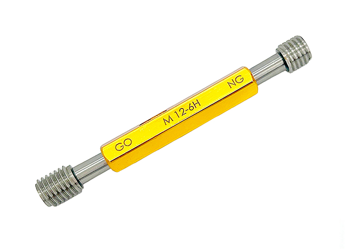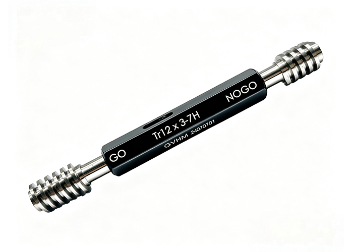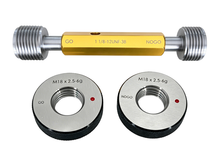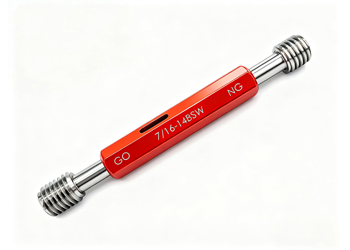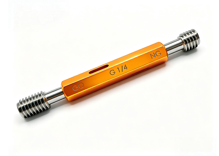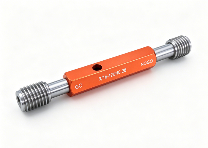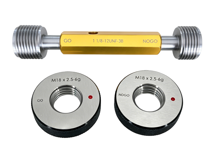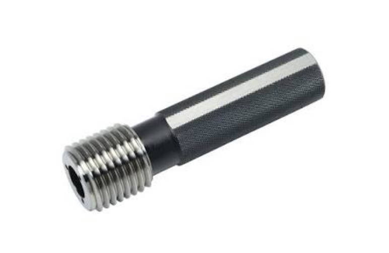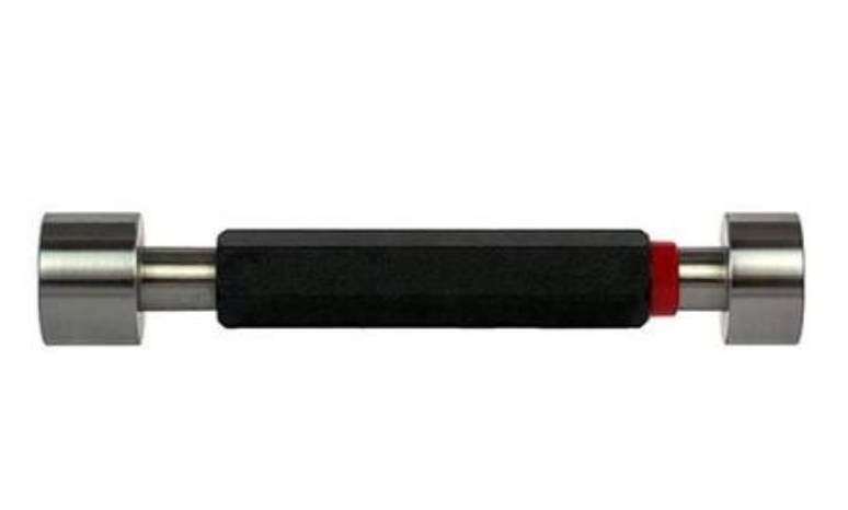
When machining internal threads, few quality inspection results are as counterintuitive as this: the “Go” plug gauge binds before reaching depth, yet the “No-Go” gauge threads smoothly into the hole. Standard inspection logic suggests that if a thread is too small, the No-Go gauge cannot enter; if it is too large, the Go gauge should pass effortlessly.
When both failures happen simultaneously, the thread does not have a single dimensional error. Instead, it has a geometric defect where functional pitch diameter and simple pitch diameter diverge. Lead errors, flank angle deviations, hole taper, and out-of-round geometry cause the Go gauge to bind on accumulated interference, while localized pitch diameter enlargement permits the truncated No-Go gauge to seat.
This guide breaks down the physical mechanics behind this gauging paradox, analyzes the four most common machining defects responsible for it, details verification steps for your standard Go / No-Go thread plug gauges, and provides a 5-step diagnostic protocol for CNC machinists and quality control personnel.
The Inspection Dilemma: How Can a Thread Fail Both “Go” and “No-Go” Tests?
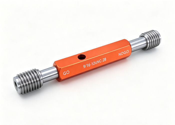
Thread inspection relies on the Taylor Principle of gauging. Under this principle, a Go gauge checks the maximum material condition across the full engagement length, evaluating composite features simultaneously. The No-Go gauge checks the minimum material condition by inspecting isolated pitch diameter with truncated crests and roots to minimize contact with other thread features.
When the Go gauge sticks and the No-Go gauge enters, it indicates that:
The composite envelope is undersized or obstructed, preventing the full-form Go gauge from passing freely.
The local pitch diameter is oversized, allowing the truncated No-Go gauge to clear the flanks.
| Parameter | Go Gauge Inspection | No-Go Gauge Inspection |
| Profile Configuration | Full thread profile across complete engagement length | Truncated thread profile spanning 2 to 3 threads |
| Feature Evaluated | Maximum material condition & functional pitch diameter | Minimum material condition & simple pitch diameter |
| Observed Defect Mechanism | Binds on cumulative lead, taper, or flank angle errors | Enters freely because local thread groove is cut too wide |
| Inspection Outcome | Rejection due to interference or binding | Rejection due to thread loose fit or over-travel |
This condition occurs when tool wear, machine misalignment, or cutting deflection distorts the thread geometry. The workpiece is non-compliant, but standard single-point tools cannot diagnose the underlying defect without isolating specific thread parameters.
Understanding Functional vs. Pitch Diameter: Why the Paradox Happens
To identify the root cause, quality engineers must distinguish between simple pitch diameter and functional (virtual) pitch diameter.
Simple Pitch Diameter: The diameter of an imaginary coaxial cylinder that cuts the thread profile where the width of the thread ridge equals the width of the thread groove.
Functional Pitch Diameter: The simple pitch diameter adjusted by the cumulative dimensional effects of lead variation, flank angle error, taper, and roundness across the full length of engagement.
| Gauge Type | Primary Measurement Scope | Response to Form Errors |
| Go Thread Plug Gauge (Full thread profile & length) | Functional pitch diameter across the full engagement length | Binds when pitch, cumulative lead, or flank angles deviate |
| No-Go Thread Plug Gauge (Truncated crests, 2–3 turns) | Simple pitch diameter over 2 to 3 thread crests | Ignores lead errors; enters if the local groove space is wide |
When an internal thread has a cumulative pitch error (lead error), every successive pitch shifts slightly relative to nominal spacing. The full-length Go gauge contacts opposite flanks simultaneously at the front and back of engagement, locking up mechanically.
However, because the machinist expanded tool offset to force the Go gauge in, the thread groove width was cut too wide. The short, truncated No-Go gauge encounters no cumulative pitch interference and drops into the oversized groove.
4 Hidden Thread Defects Causing False Gauge Readings
When standard tooling produces this gauging conflict, the issue typically traces back to one of four machining and geometric defects:
1. Cumulative Lead Error (Pitch Deviation)
Lead error occurs when the linear advance per revolution fails to match nominal pitch specifications. Common causes include:
Backlash or thermal drift in the CNC ballscrew.
Incorrect threading feed programming.
Tool push-off on long-reach boring bars.
A positive or negative lead error consumes internal thread clearance rapidly over multiple threads. While the thread space itself may be cut wide, the accumulated spacing error locks the full-length Go plug gauge.
2. Flank Angle Distortion from Worn Inserts
Threading inserts experience edge chipping and flank wear at the depth-of-cut line. When the included angle changes (e.g., departing from a nominal 60° profile), the gauge teeth wedge against the modified slope rather than seating at the pitch line.
This angular discrepancy adds “virtual size” to internal threads, preventing the Go gauge from seating. If the operator compensates by taking additional radial passes, the pitch line expands, allowing the No-Go gauge to thread in.
3. Tapered Hole or Bell-Mouthing (Entry Flaw)
Chips packing at the bottom of blind holes or deflection on entry can generate tapered internal threads:
Bell-mouthing: The hole entrance is oversized, permitting the No-Go gauge to enter 2 to 3 turns before stopping.
Positive Taper: The thread narrows toward the bottom, causing the Go gauge to stick halfway through its stroke.
Because gauging standards generally permit a No-Go gauge to enter up to 2 or 3 turns before rejection, an entry taper creates conflicting readings between entrance and full-depth inspection.
4. Out-of-Roundness, Drunken Threads, or Thread Lobing
Workpiece distortion inside three-jaw chucks often induces 3-lobed (triangular) out-of-roundness. While a two-point caliper or micrometer measurement might appear normal, the geometry forms a lobed profile.
Similarly, axial spindle runout creates “drunken threads”—leads that wobble cyclically within a single revolution. Both conditions prevent full-circumference Go gauges from rotating freely while providing localized gaps that accept No-Go gauges.
| Observed Gauge Reaction | Probable Geometric Defect | Primary Shop Floor Source |
| Go binds after 2–3 turns; No-Go enters freely | Cumulative lead error (pitch shift) | Machine ballscrew wear, encoder scaling, or excessive bar overhang |
| Go binds immediately; No-Go enters easily | Flank angle error or root burrs | Chipped insert tip, incorrect tool center height, or material pickup |
| No-Go enters entrance; Go binds near bottom | Bell-mouthed or tapered hole | Boring bar deflection on initial cut, uneven coolant delivery |
| Go binds intermittently; turns stick then loosen | Out-of-roundness / clamping lobing | Excessive chuck jaw pressure, thin-walled part distortion |
Is Your Gauge the Culprit? Verifying Tool Wear and Technique
Before resetting CNC offsets or scrapping workpieces, verify that your inspection tools and procedures meet calibration criteria. Using worn or unverified tools often introduces false failures.
| Verification Item | Inspection Method | Acceptance Target |
| Cleanliness | Flush threads with solvent and wipe with a non-metallic brush | Complete removal of chips, coolant varnish, and abrasive grit |
| Gauge Wear | Check Go gauge front threads under an optical comparator | Pitch diameter remains within standard wear-limit tolerance |
| Calibration Status | Review active metrology certification records | Within active calibration cycle per ISO or ASME specifications |
| Thermal Equilibrium | Soak workpieces and gauges in the inspection room | Stable at 20°C (68°F) nominal reference temperature |
| Operator Torque | Apply manual, two-finger rotation without tools | Smooth engagement without mechanical force or lever arms |
Gauge Wear Limits and Calibration Cycles
Go gauges absorb substantial friction because they engage the full depth of every accepted part. Over extended production runs, the front threads wear undersized, develop burrs, or pick up galling material from stainless steel or aluminum alloys.
Conversely, an old or improperly ground No-Go gauge may have worn undersized, allowing it to enter holes it should reject. High-precision manufacturing environments benefit from precision-ground thread gauges with documented traceability to verify pitch diameter tolerances.
Gauge Expansion, Thermal Drift, and Operator Force
Thermal variation alters thread fit:
A warm workpiece taken straight from a cutting fluid cycle has an expanded internal cavity.
A cold gauge inserted into a hot aluminum workpiece can seize as heat transfers into the gauge steel.
Gauging must occur after parts stabilize at standard reference temperatures (nominally 20°C / 68°F). Additionally, thread plug gauges must turn smoothly using light finger torque; applying mechanical force with pliers or wrenches wedges a Go gauge into minor flank misalignments, damaging both the part and the gauge.
5-Step Diagnostic Protocol: How to Isolate and Resolve the Error
When a machining setup produces this gauge conflict, follow this sequential protocol to determine whether the problem lies in tool wear, machine kinematics, or gauge maintenance:
| Step | Action Area | Key Diagnostic Tasks |
| 1 | Clean and Visual Inspection | Degrease the hole; check roots and crests with a bore scope for torn metal, burrs, or built-up edge. |
| 2 | Gauge Condition Cross-Check | Test the part using a calibrated secondary backup set of durable carbide or hardened steel thread gauges at 20°C. |
| 3 | Multi-Parameter Geometry Check | Measure simple pitch diameter with an internal pitch micrometer; inspect lead and flank angles on a CMM or optical comparator. |
| 4 | Tooling & Machine Kinematics Audit | Inspect threading insert tip for chipping; re-center tool height to spindle center line; verify ballscrew pitch tracking. |
| 5 | CNC Offset & Feed Calibration | Resolve pitch lead errors first via feed per rev; then adjust radial depth offsets in controlled increments. |
Step 1: Clean and Visually Inspect the Hole
Blow out chips and wash away gummy coolant residues using a degreaser. Use a bore scope or lighted loupe to check the crests and roots for micro-burrs, torn threads, or material buildup.
Step 2: Cross-Check with a Calibrated Backup Gauge
Switch to a secondary, calibrated set of durable carbide or hardened steel thread gauges. If a fresh gauge passes without binding, the production gauge has accumulated chips, burrs, or mechanical damage.
Step 3: Measure Independent Parameters via Variable Inspection
Fixed Go/No-Go limit gauges can only confirm whether a part is within boundary limits; they cannot indicate why a feature failed. Use an internal pitch micrometer, an optical comparator on cut sections, or a coordinate measuring machine (CMM) to measure:
Simple pitch diameter at the top, middle, and bottom of the hole.
Pitch/lead error over a span of 5 to 10 threads.
Included flank angle.
Step 4: Audit Machine Kinematics and Tooling Alignment
Insert Condition: Replace the threading insert if any edge chipping or crater wear is visible under magnification.
Center Height: Verify the threading tool sits precisely on the workpiece spindle center line. Off-center threading tools distort the flank angle.
Rigidity: Reduce tool overhang to minimize deflection during cutting.
Step 5: Adjust CNC Offsets and Feed Rates Sequentially
Do not adjust radial offsets and feed rates at the same time:
Correct the thread pitch/lead first by checking machine encoder scaling and program feed per revolution.
Once pitch progression is verified, adjust radial tool offsets in small increments until the Go gauge turns freely without loosening the fit to the point where the No-Go gauge enters.
Key Takeaways
The Core Mechanism: A Go gauge binds while a No-Go gauge enters because functional pitch diameter (affected by form, lead, and angle errors) is too small, while simple pitch diameter (groove width) is too large.
Primary Defect Source: Tool wear and cumulative lead error are the most frequent causes of false gauge engagement.
Taylor Principle Limitations: Fixed limit gauges determine acceptance, not causation. When gauges provide contradictory readings, switch to variable parameter measurement (pitch micrometers, CMM, or optical comparators).
Gauge Integrity: Always rule out dirty, damaged, or uncalibrated inspection tools before adjusting machine axes or scrapping production batches.
Frequently Asked Questions (FAQ)
Can a thread pass the Go gauge if the pitch diameter is undersized?
No. An undersized internal thread pitch diameter will prevent the full-form Go plug gauge from entering. The Go gauge represents the maximum material condition (smallest permissible internal hole boundary). If the simple pitch diameter is undersized, the gauge will bind immediately at the entrance.
How many turns is a No-Go gauge allowed to enter before the part fails?
Under most international standards (such as ISO 1502 and ASME B1.2), a No-Go thread plug gauge must not enter the workpiece by more than two or three complete turns. Entering beyond three turns indicates that the simple pitch diameter is oversized, requiring part rejection or engineering disposition.
Does excessive coating or plating thickness trigger this paradox?
Excessive plating thickness typically causes the Go gauge to bind, but it prevents the No-Go gauge from entering as well, because uniform coatings reduce the internal space across all thread flanks. However, if an operator over-cuts the thread prior to plating to compensate for coating buildup and the plating applies unevenly (heavier at the opening than the interior), the No-Go gauge may enter the poorly plated interior while the Go gauge binds at the tight entrance.
When should a quality department retire a worn thread plug gauge?
A thread plug gauge must be removed from service whenever calibration reveals that the Go member has worn below its designated wear-limit tolerance, if teeth show mechanical chipping or burrs, or if the No-Go gauge has worn past acceptable dimensional limits.