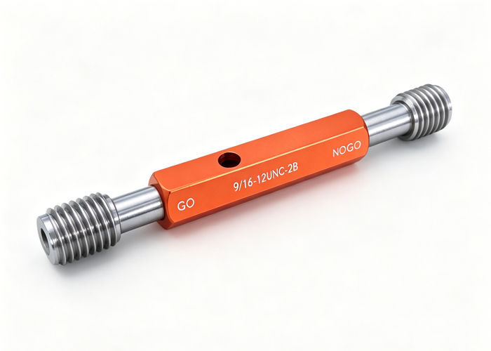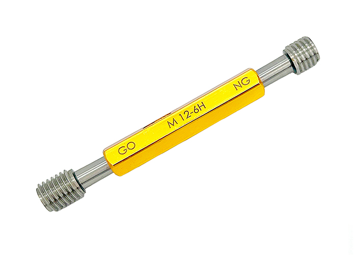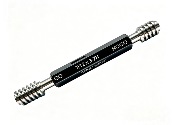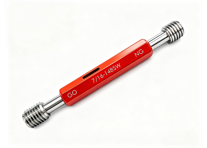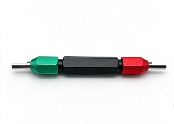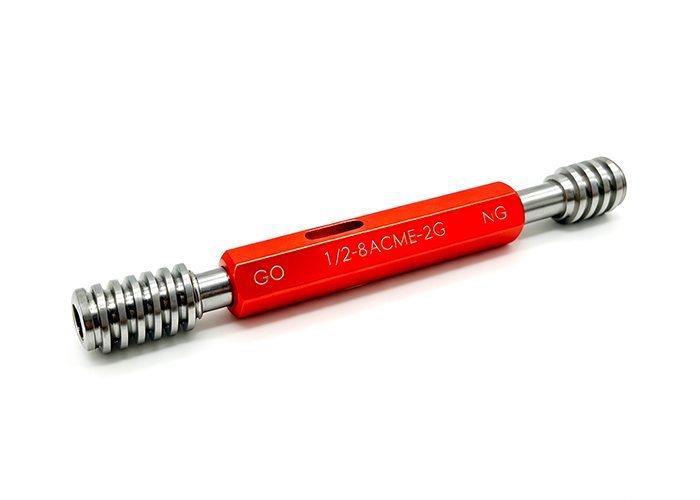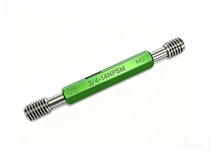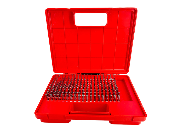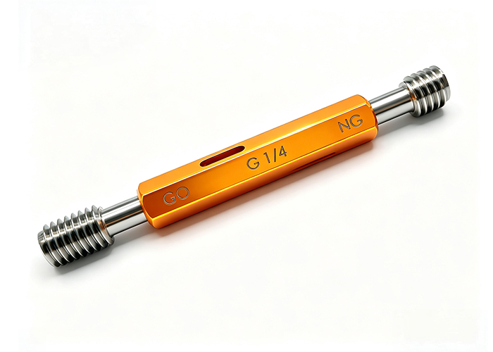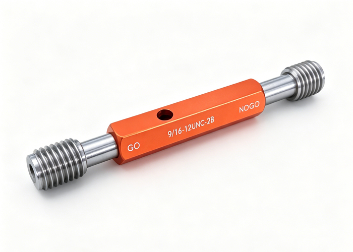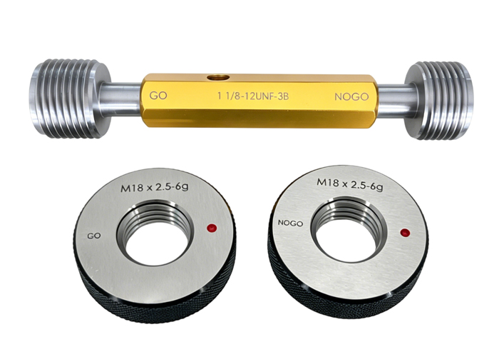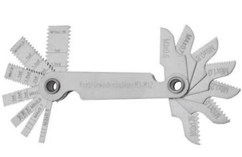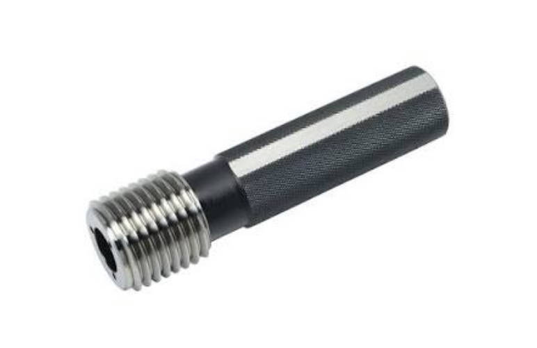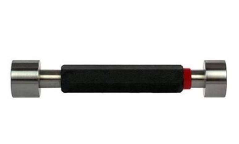
To order custom thread gauges that function correctly on the first production run, you must provide your OEM manufacturer with complete geometric boundaries, plating allowances, and inspection reference standards. The most critical variables affecting gauge accuracy are nominal size, thread profile, pitch, pitch diameter limits for both GO and NO-GO members, and the exact plating condition of the workpiece. Omitting even one dimensional variable forces manufacturers to rely on standard assumptions that frequently do not match custom part designs.
This guide outlines the complete engineering specifications, tolerance designations, and dimensional checklists required to order non-standard thread plug and ring gauges without engineering delays or inspection discrepancies.
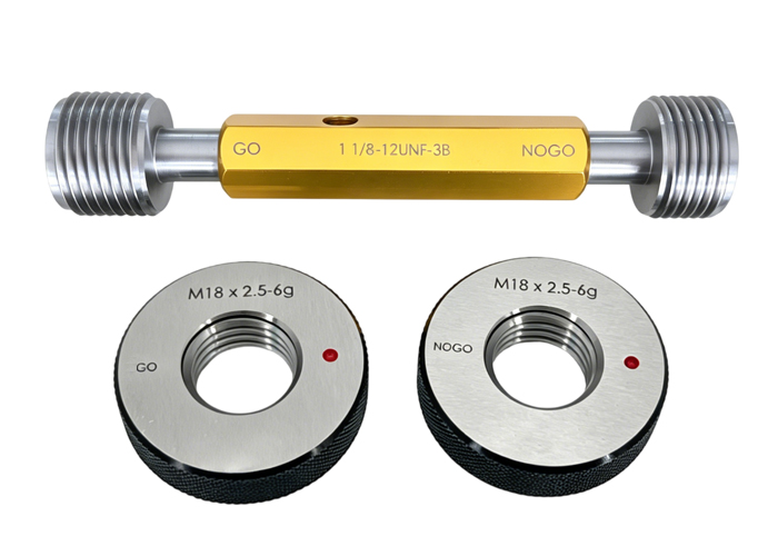
The Cost of Incomplete Specifications in Custom Thread Gauge Procurement
Procuring non-standard thread gauges carries a significantly higher risk of lead-time inflation than purchasing catalog tools. When a purchase order specifies only nominal diameter and pitch—such as an unstandardized “M42 x 1.2 special”—without specifying pitch diameter limits or reference standards, the manufacturing process stalls immediately.
| Risk Category | Immediate Manufacturing Bottleneck | Operational Impact on Buyer |
| Engineering Holds | Inability to calculate grinding wheel dressing parameters or select master blanks | Order paused; quoting and production lead times extended by days or weeks |
| Scrapped Blanks & Parts | OEM uses standard nominal tolerances (e.g., 6H/6g) that do not match custom depths | Finished gauges misclassify acceptable production parts as out-of-spec scrap |
| Calibration Rejections | Metrology labs lack an authorized engineering standard or print to verify limits | Gauges cannot receive traceable certification for ISO-compliant quality audits |
Clear technical documentation provided at the inquiry stage eliminates drawing revisions and ensures the finished inspection tool matches the operational requirements of your production floor.
Core Engineering Parameters Required for Custom Thread Gauges
Every custom thread gauge design starts with foundational dimensional and geometric parameters. Both thread plug gauges (for internal parts) and thread ring gauges (for external parts) require unambiguous definitions of these core features.
| Parameter Category | Required Engineering Specification | Practical Application & Notes |
| Basic Thread Form & Included Angle | Exact tooth profile: 60° (Metric, UN), 29°/30° (ACME, Trapezoidal), Whitworth (55°), or Buttress (e.g., 7°/45°) | Governs tool dressing profiles and root/crest clearance geometry. |
| Pitch & Lead (TPI) | Axial pitch in mm ($P$) or Threads Per Inch (TPI); lead for multi-start threads | For multi-start threads, explicitly define both pitch (crest-to-crest) and lead (axial travel per turn). |
| Thread Direction | Right-Hand (RH) or Left-Hand (LH) | OEMs default to RH unless LH is explicitly marked on drawings and purchase orders. |
| Pitch Diameter (PD) Limits | Numerical min/max limits for GO member and NO-GO member | Eliminates reliance on arbitrary standard fits; establishes legal pass/fail boundaries. |
| Major & Minor Diameters | Plug: Max major diameter on GO; truncation on NO-GO Ring: Min minor diameter clearance | Prevents root/crest interference so the gauge verifies flank fit rather than diameter clearance. |
| Envelope & Reach Constraints | Max gauge length, shank reach, counterbore depth, or chip flutes | Necessary for recessed internal threads or parts with shoulder obstructions. |
Plug Gauges vs. Ring Gauges: Differing Spec Requirements
Thread plug gauges inspect tapped internal holes, while thread ring gauges inspect threaded external shafts or fasteners. Because their contact geometries differ fundamentally, each requires specific supplementary data on your RFQ drawing.
| Parameter Category | Custom Thread Plug Gauge (Internal Threads) | Custom Thread Ring Gauge (External Threads) | Engineering Note |
| Primary Reference Feature | Pitch diameter and major diameter boundaries | Pitch diameter and minor diameter clearance | Ring gauges require calibrated setting plugs for initial sizing and future recalibration. |
| Hole / Feature Type | Blind hole vs. Through hole | Stepped shaft, shoulder clearance, or runout neck | Blind holes require short front pilots or chip flutes to inspect threads to the bottom. |
| Wear Allowance Type | Added to the GO member pitch diameter | Subtracted from the GO ring pitch diameter | Dictates tool life before the gauge wears beyond permissible calibration limits. |
| Mounting / Style | Taperlock, Reversible pin, or Trilock handle | Solid round blank or adjustable split ring blank | Reversible plug designs allow flipping the gauge member when the front threads wear out. |
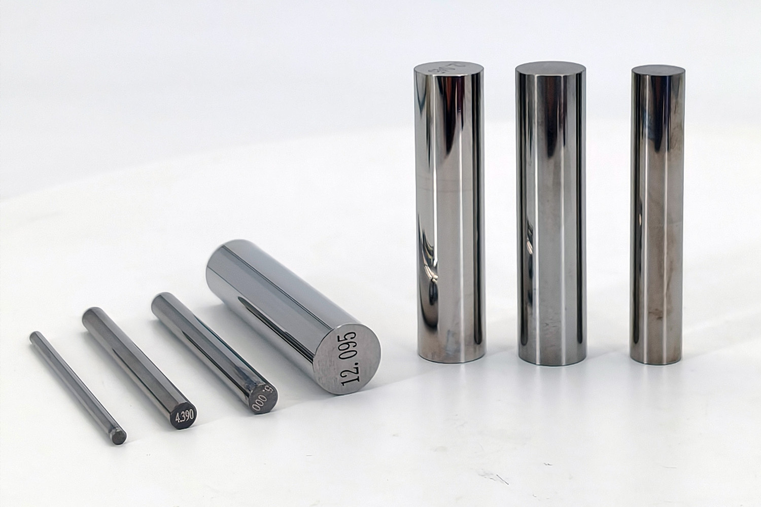
When ordering custom ring gauges from an OEM thread gauge manufacturing partner, determine whether you require a matching setting plug gauge (Set Plug). Setting plugs establish the baseline measurement for adjustable ring gauges and serve as the physical audit standard during quality disputes.
Critical Edge Cases: Coating Allowances, Materials, and Calibration Standards
Standard gauges fail most frequently due to uncalculated surface treatments, thermal wear, and missing calibration traceability. Addressing these three variables eliminates non-conformance disputes between machine shops and OEM vendors.
Pre-Plate vs. Post-Plate Pitch Diameter Allowances
Electroplating, anodizing, and phosphating add surface thickness that significantly alters thread pitch diameter. On a standard 60° thread flank, the change in pitch diameter is four times the plating thickness per side:
$$\Delta PD = 4 \times t_{\text{plating}}$$
| Plating State | Description & Gauge Offset Requirement | Typical Application |
| Pre-Plate Dimensions | Gauge is manufactured with special offsets (enlarged for internal threads, reduced for external threads) to account for coating buildup | In-process quality control at CNC machining stations before sending parts to plating |
| Post-Plate Dimensions | Gauge is manufactured to final blueprint pitch diameter limits | Final QA inspection after electrolytic plating, anodizing, or protective coating |
Tool Steel Selection and Wear Resistance Needs
Gauge longevity depends on pairing the gauge material with the abrasive characteristics of the workpiece.
| Material Option | Typical Hardness / Characteristics | Recommended Use Case |
| Standard Bearing / Tool Steel (e.g., GCr15 / 52100) | 60–62 HRC; high dimensional stability | General-purpose steels, brass, aluminum, and low-to-medium batch runs |
| High-Speed Steel (HSS) | Enhanced toughness and surface wear resistance | Abrasive stainless steels, alloy steels, and moderate production runs |
| Tungsten Carbide Inserts | Extreme abrasion resistance; maximum hardness | High-silicon aluminum, cast iron, abrasive composites, and continuous automated lines |
Note: Specific alloy grades and cryo-stabilization procedures vary by manufacturer and must be verified during technical quotation.
Traceability and Calibration Standard Requirements
| Documentation Level | Included Verification Data | Recommended Application |
| Certificate of Conformance (CoC) | Statement verifying the gauge conforms to purchase order specifications | General commercial machining; non-regulated industrial components |
| Standard Inspection Report | Recorded actual values for pitch diameter, major/minor diameters, and lead | In-house QA audits, automotive tier suppliers, precision toolrooms |
| ISO/IEC 17025 Accredited Certificate | Fully traceable metrological data with expanded measurement uncertainty | Aerospace, medical implants, defense, and safety-critical assemblies |
Complete RFQ Submission Checklist: What to Send to Mihe
To receive an accurate engineering review and commercial quote without delay, compile your technical inquiry using the structured checklist below:
| Requirement Group | Parameter to Provide | Specific Details / Options |
| 1. Thread Definition & Drawing | Thread Designation | Special Metric, Modified Stub ACME, UN Special, Whitworth, Buttress |
| Size & Lead Parameters | Nominal diameter, axial pitch (or TPI), and lead (for multi-start) | |
| Pitch Diameter Limits | Explicit GO min/max limits and NO-GO min/max limits | |
| Flank Geometry | Included tooth angle (e.g., 60°, 55°, 29°, 7°/45°) | |
| Hand Orientation | Right-Hand (RH) or Left-Hand (LH) | |
| 2. Part Condition & Process | Processing Stage | Pre-plating dimensions or final post-plating dimensions |
| Coating Allowance | Expected coating thickness range if pre-plate offset is needed | |
| Workpiece Material | Mating part alloy (e.g., 316L SS, 6061-T6 Al, ductile iron) | |
| 3. Tool Style & Physical Constraints | Gauge Style | Double-end plug, single-end GO/NO-GO, or ring gauge |
| Handle / Blank Type | Taperlock, Trilock, Reversible wire-type, or solid/adjustable ring | |
| Reach & Clearance | Extended shank length, counterbore pilots, or blind-hole chip flutes | |
| 4. Quality & Calibration Standards | Reference Standard | Baseline engineering standard (ISO, ASME, DIN, or JIS) |
| Calibration Protocol | Standard Certificate of Conformance vs. ISO 17025 accredited report | |
| Master Setting Standard | Matching setting plug requirements (for ring gauge orders) |
Consolidating these parameters into your initial technical RFQ enables manufacturers to evaluate machining feasibility, select optimal tool steel stock, and verify inspection standards immediately. For critical applications, partnering with a supplier that maintains comprehensive machining and metrology capabilities for precision thread gauges ensures your non-standard tooling maintains dimensional integrity across extended production cycles.
Key Takeaways
| Consideration | Core Takeaway |
| Avoid Ambiguous Callouts | Stating only “M38x1.5 special” stops production; explicit pitch diameter limits are required for both GO and NO-GO members. |
| Calculate Plating Growth | On 60° threads, the pitch diameter shifts by four times the single-side plating thickness ($\Delta PD = 4 \times t_{\text{plating}}$). |
| Distinguish Hole Types | Internal blind holes require chip grooves or shortened front pilots to verify threads to the bottom without bottoming out. |
| Establish Calibration Authority | Non-standard gauges must reference a recognized standard framework (ASME, ISO, DIN) to allow accredited lab verification. |
| Pair Ring Gauges with Set Plugs | Thread ring gauges cannot be measured across internal pitch diameters with standard micrometers; setting plugs are required for verification. |
Frequently Asked Questions (FAQ)
Can an OEM manufacture a custom thread gauge using only a sample threaded part?
Reverse engineering a thread gauge solely from a physical part carries measurement risks. While pitch and nominal diameter can be measured via optical comparators and thread wires, determining the original engineering tolerance class and pitch diameter limits (GO vs. NO-GO) requires an engineering drawing. Supplying a physical mating part alongside a formal 2D drawing is helpful, but the drawing remains the legal inspection baseline.
What is the default tolerance class if a custom drawing does not specify one?
There is no universal default tolerance for non-standard threads. If an RFQ lacks tolerance data, the OEM must pause the order to confirm whether standard industrial baselines (such as ISO 965 medium fit 6H/6g or ASME B1.1 Class 2B/2A) apply, or if custom limits are required.
How does custom thread gauge pricing compare to standard catalog tools?
Custom thread gauges require dedicated toolpath programming, individual CNC thread grinding setups, custom dressing of grinding wheels, and individual metrology verification. Consequently, non-standard gauges carry a higher unit cost and longer lead times than mass-produced, off-the-shelf standard sizes.
Why do thread ring gauges require matching setting plugs?
Unlike solid plug gauges, thread ring gauges cannot be measured directly across their internal pitch diameter using standard micrometers or three-wire systems with sufficient accuracy. A precision-ground setting plug gauge serves as the master physical standard to calibrate, adjust, and periodically verify the ring gauge’s internal geometry.
When are tungsten carbide thread gauges worth the additional investment?
Carbide gauges provide significantly greater wear resistance than tool steel. They are economically justified in high-volume, automated machining lines or when inspecting abrasive materials such as high-silicon cast aluminum alloys, cast iron, or abrasive composites that rapidly wear hardened steel tools out of calibration.