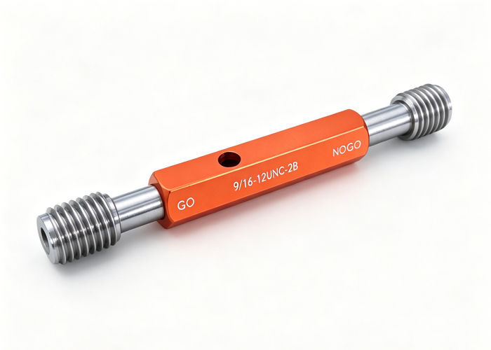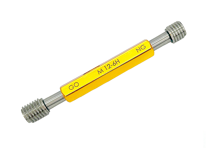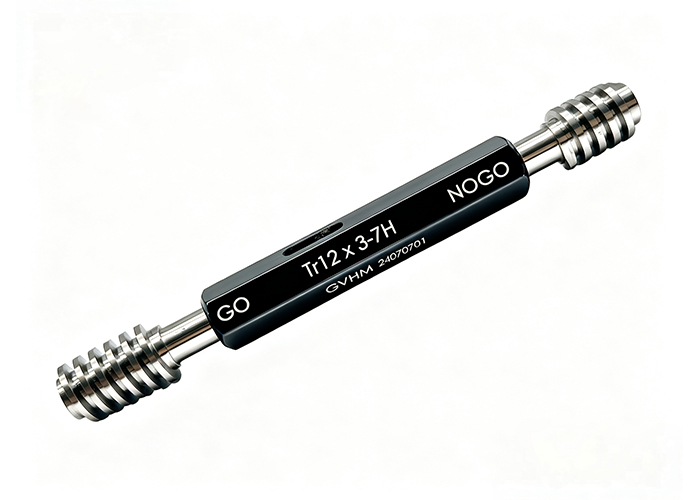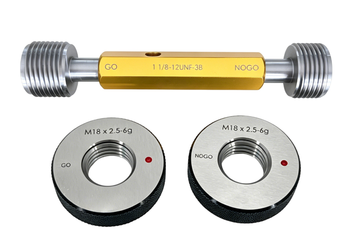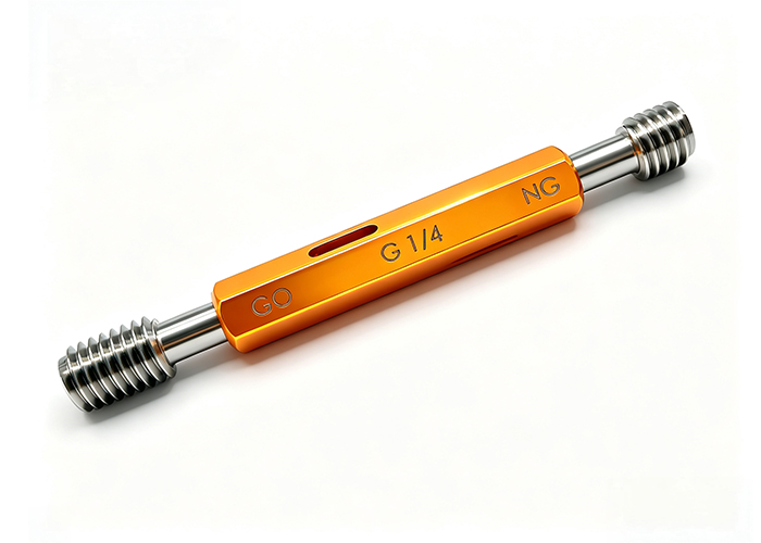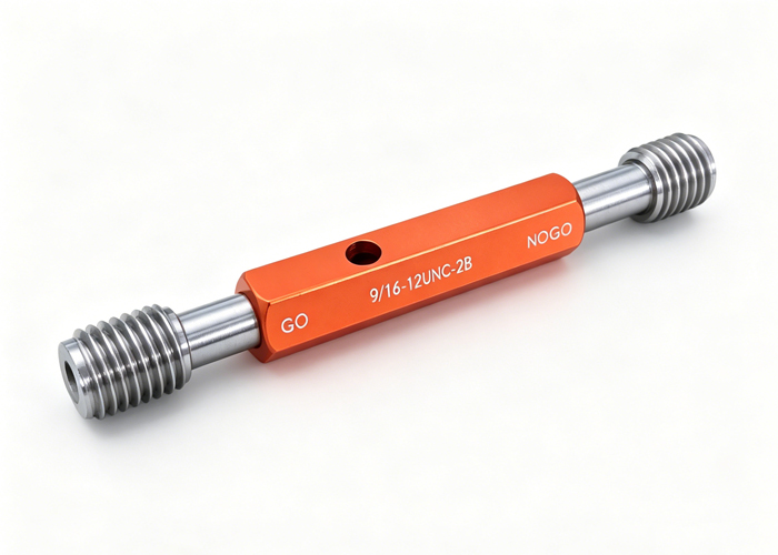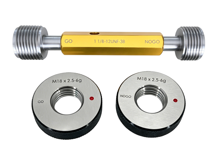
Inspecting tapped blind holes frequently leads to false part rejections, prematurely worn gauges, and unverified engagement depths. The primary cause is mechanical interference: compressed chips packing into the bottom threads or drill point runout that stops a Go member before reaching full engagement depth. Accurately qualifying internal threads in blind holes requires isolating chip accumulation from thread profile errors, enforcing strict hole preparation procedures, and selecting specialized tooling configurations such as dirt-groove or depth-indicating plug gauges. and selecting specialized tooling configurations such as dirt-groove or depth-indicating plug gauges.
This guide examines the mechanics of blind hole gauging failures, outlines a shop-floor diagnostic workflow to verify true thread depth versus debris obstruction, and reviews tooling options engineered to maintain gauge life and inspection throughput.
The Blind Hole Conundrum: Why Conventional Thread Gauging Fails
Standard thread inspection relies on the free engagement of a Go plug gauge to verify functional pitch diameter, which reflects the combined effects of pitch diameter, flank angle, lead, and other thread element deviations. In a through-hole, displaced swarf and cutting fluid drain freely through the bottom of the bore. In a through-hole, displaced swarf and cutting fluid drain freely through the bottom of the bore. In a blind hole, however, the closed bottom creates a containment zone where residual chips, coolant residue, and tap runout concentrate.
When using standard precision thread plug gauges in blind hole applications, three recurring issues compromise measurement accuracy:
Swarf Compaction: As a solid Go plug enters the hole, it functions like a piston. It pushes loose particulate ahead of its leading threads, compressing chips into the final root and crest profiles.
Inconclusive Thread Engagement Depth: Standard cylindrical thread gauges verify functional pitch diameter, not linear depth. Operators often rely on hand feel, visual scribes, or separate depth rods, leading to inconsistent depth verification across shifts.
Abrasive Flank Wear: Trapped chips wedged between the internal thread flanks and the hardened gauge teeth create micro-galling and accelerated abrasive wear, reducing the gauge’s calibration interval.
| Inspection Factor | Through-Hole Machining | Blind Hole Machining |
| Chip Evacuation Path | Continuous downward or upward exit | Upward exit only; prone to bottom packing |
| Tap Runout Clearance | Not constrained by bore bottom | Constrained by drill depth minus tap chamfer |
| Primary Failure Mode | Tool wear / oversize pitch diameter | False undersize / short thread engagement |
| Gauge Wear Pattern | Uniform across full engagement length | Severe front-engagement flank abrasion |
Diagnosing False Rejections: Chip Packing vs. Incomplete Threading
When a Go thread gauge stops short of the specified engagement depth, machinists and QC inspectors must determine whether the root cause is dimensional (a shallow tap cycle or incorrect pitch diameter) or mechanical (debris blockage).
| Visual Bore Condition | Secondary Diagnostic Action | Tactile Resistance Profile | Root Cause Identification | Corrective Action |
| Visible chips packed in bottom threads | Execute bottom-up high-pressure solvent flush, blow dry, and re-test with Go gauge. | Gauge passes smoothly to target depth after cleaning. | Chip Contamination (False Rejection): Thread geometry is conforming; chips caused premature binding. | Clear production lot; update pre-inspection hole flushing protocols. |
| Cavity clean to drilled relief | Re-insert Go gauge manually by hand; evaluate the stop profile. | Rigid, hard metallic stop (zero rotational spring-back). | Insufficient Thread Depth: Tapping stroke ended prematurely, drilled relief depth is shallow, or lead chamfer is incomplete. | Inspect tap depth stroke, check drill point relief, or switch to a bottoming tap. |
| Cavity clean to drilled relief | Re-insert Go gauge manually by hand; evaluate the stop profile. | Spongy, gradual binding (slight elastic rotational spring-back). | Tapered Pitch Diameter or Crushed Swarf: Hole shrinkage toward the bottom, worn tap crests, or micro-chips embedded in flanks. | Check tap flank wear, verify tool pitch diameter with optical comparators, and clean thread roots with an agitation brush. |
Distinguishing Resistance Profiles
Rigid Stop: If the gauge turns freely and then hits a solid, unyielding mechanical stop with zero rotational spring-back, the issue is typically dimensional: the hole was drilled shallow, the tap stroke stopped short, or an intermediate tap was used instead of a bottoming tap.
Spongy or Springy Resistance: If the gauge gradually tightens over the final one to two turns and displays a subtle spring-back when rotational torque is released, debris is almost certainly packing between the leading threads and the bottom of the hole.
Standard Operating Procedure: Pre-Inspection Cleaning and Verification
Relying on standard low-pressure air nozzles often worsens chip accumulation in deep blind bores by packing swarf deeper into thread roots. Implement this four-step preparation procedure before applying a thread plug gauge to tight-tolerance blind holes:
Targeted Coolant/Solvent Flush: Direct a narrow-tip nozzle fully to the bottom of the blind cavity. Flush from the bottom upward using filtered solvent or high-pressure machine coolant to suspend trapped chips.
Mechanical Swarf Agitation: For blind holes with high aspect ratios (depth-to-diameter greater than 2.5:1), insert a non-metallic, bore-matched bristle brush to dislodge particles clinging to the 60-degree flank roots.
Deep-Bore Vacuum or Venturi Extraction: Rather than blowing air downward into the cavity, use a vacuum or a dual-path air wand that introduces air on one side while allowing suspended chips an uninhibited exit path.
Visual and Tactile Pre-Check: Confirm that the drilled bottom clearance accommodates the incomplete threads produced by the tap chamfer. A bottoming tap typically leaves one to two incomplete threads; if the design requires full thread engagement within one pitch of the bottom, thread milling or specialized relief undercuts must be confirmed before gauging.
Tooling Upgrades: Specialized Thread Gauge Designs for Blind Holes
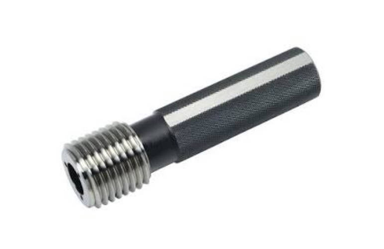
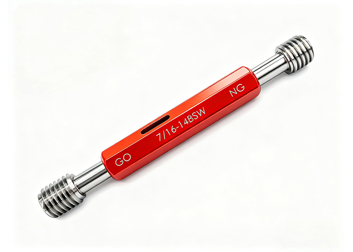
Standard solid Go/No-Go plug members are not optimized for production blind hole inspection. Upgrading to purpose-built industrial thread gauges significantly reduces false failure rates and eliminates secondary depth-measurement operations.
1. Thread Gauges with Dirt Grooves (Fluted Plugs)
These gauges feature one or more longitudinal relief flutes ground across the perimeter of the Go thread profile, interrupting the full circumference of the teeth.
Mechanism: The flutes provide a containment channel for residual chips, cutting fluids, and particulate matter. As the gauge threads in, debris is swept into the flutes rather than compressed into the thread flanks.
Best Used For: Cast iron, cast aluminum, and materials producing discontinuous, crumbly chips.
2. Integrated Thread Depth Gauges
These tools combine a precision-ground threaded member with an outer sprung sleeve calibrated to measure linear travel.
Mechanism: The sleeve sits against the workpiece face while the threaded core rotates to the bottom of the tapped hole. Thread engagement depth is read directly via a vernier scale, digital readout, or stepped go/no-go lines on the body.
Best Used For: High-volume aerospace and automotive housings with strict minimum/maximum thread engagement tolerances.
| Gauge Configuration | Primary Mechanism | Inspection Benefit | Operational Limitation |
| Standard Solid Plug | Full-form continuous profile | Verifies functional pitch diameter | Prone to debris jamming; no direct depth readout |
| Dirt-Groove Plug | Fluted thread profile along body | Clears loose particulate; prevents false stops | Higher manufacturing cost; requires regular flute cleaning |
| Depth-Indicating Plug | Threaded plug with calibrated sleeve | Simultaneously checks pitch diameter and depth | Requires flat reference surface perpendicular to bore |
| Stepped Depth Go Plug | Etched step or notch on Go member | Quick visual check of minimum engagement | Subject to parallax error; visual verification only |
Engineering Considerations When Sourcing Blind Hole Thread Gauges
Procuring gauging for blind hole operations requires looking beyond nominal diameter, pitch, and class of fit. Quality and tooling engineers should confirm the following technical variables with gauge manufacturers:
Front Chamfer Configuration: Standard Go plugs feature a lead-in chamfer of approximately 0.5 to 1.5 pitches to facilitate hole entry. In blind holes with minimal bottom clearance, this lead-in cannot engage the incomplete threads left by a bottoming tap. Specifying a truncated or shortened front chamfer must be carefully balanced, as an aggressive lead-in removal increases the risk of cross-threading during manual inspection.
Relief Undercut Requirements: For stepped or depth-reading gauges, verify that the transition between the gauge shank and the threaded body contains an adequate relief grind to avoid bottoming on unchamfered hole edges.
Tool Material and Hardness: Blind hole inspection accelerates abrasive wear due to trapped particles. High-speed steel (HSS) with cryogenic stabilization or specialized surface treatments (such as titanium nitride or chrome plating) provides extended operational life over baseline carbon steel gauges. In automated or severe-wear environments, solid carbide Go members should be evaluated.
Calibration Frequency Offsets: Because blind hole gauging involves higher friction and intermittent debris contact, establish tighter calibration intervals for blind-hole Go members compared to through-hole tools running on the same shift.
When non-standard depths, unusual pitch combinations, or aggressive bottom-clearance constraints occur, consider custom thread gauge solutions configured with application-specific flute profiles and tailored lead-in geometry.
Practical FAQ: Blind Hole Thread Quality Control
Can an operator grind down the front chamfer of a standard Go plug gauge to measure deeper into a blind hole?
Modifying a thread gauge on a shop-floor bench grinder voids its calibration certificate and risks damaging the tool’s metallurgy. Grinding removes the surface hardness profile, alters the pitch diameter lead geometry, and creates burrs that will gall internal component threads. Truncated lead-in gauges should always be ground and certified by a tool manufacturer.
Why does a Go gauge pass on a CNC machine spindle check but fail at the manual QA bench?
This discrepancy is typically driven by temperature and cleanliness. On the machine, residual warm cutting oil and machine vibration may allow the gauge to bypass minor chip packing. Once the part cools at the inspection bench, thermal contraction narrows tolerances, and drying coolant hardens swarf into the thread roots, preventing full gauge entry.
How much clearance is required between the end of full threads and the bottom of the drill point?
As a general rule for tapped blind holes, the drilled depth should exceed the required full thread depth by at least three to five thread pitches when using standard bottoming taps. If thread milling is used, this clearance can often be reduced, though process setup and chip evacuation needs must always be confirmed prior to final part release.
Key Takeaways
False Rejections Stem from Trapped Swarf: Debris packing in the bottom of closed bores mimics pitch diameter undersizing by halting Go gauges before full depth is reached.
Diagnose by Resistance Behavior: An immediate, rigid mechanical stop indicates inadequate machining depth, while a spongy, binding resistance indicates compressed chips.
Standardize Swarf Extraction: High-pressure bottom-up flushing combined with vacuum or venturi extraction provides the clean hole environment needed for valid inspection.
Fluted Gauges Reduce Scrap Rates: Thread gauges engineered with dirt flutes prevent chip compaction along the flanks, protecting tools and reducing false failures.
Depth-Indicating Tools Streamline Inspection: Combining thread engagement verification and depth measurement into a single gauging operation eliminates secondary measuring steps and reduces human error.
FAQ
Q: What is the main cause of false failures during blind hole thread inspection?
A: The most frequent cause is loose machining chips compacted into the bottom thread roots by the flat face of a standard Go plug gauge, which stops the gauge prematurely.
Q: How can QC operators distinguish between shallow thread depth and chip obstruction?
A: Check the resistance feel upon bottoming. Incomplete thread depths stop the tool abruptly with zero mechanical play, whereas chip buildup creates a gradual, cushioned binding resistance.
Q: What is a dirt groove on a thread plug gauge?
A: A dirt groove is a longitudinal channel ground through the Go threads of a plug gauge that gathers loose chips and coolant residue, preventing debris from jamming between the gauge teeth and the internal thread.
Q: Does inspecting blind hole threads require specialized calibration routines?
A: Yes. Because blind holes trap abrasive particles that accelerate wear on the front teeth of the Go member, these gauges require more frequent calibration checks than gauges used exclusively for through-holes.